
User Manual
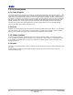

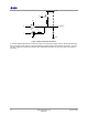
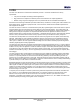
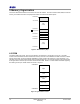
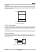
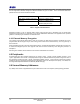
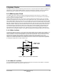
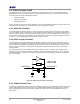
Table Of Contents
- 1 Introduction
- 2 Pin Configurations
- 3 CPU
- 4 Memory Organisation
- 5 System Clocks
- 6 Reset
- 7 Interrupt System
- 8 Wireless Transceiver
- 9 Digital Input/Output
- 10 Serial Peripheral Interface
- 11 Timers
- 12 Pulse Counters
- 13 Serial Communications
- 14 JTAG Debug Interface
- 15 Two-Wire Serial Interface
- 16 Four-Wire Digital Audio Interface
- 17 Random Number Generator
- 18 Sample FIFO
- 19 Intelligent Peripheral Interface
- 20 Analogue Peripherals
- 21 Power Management and Sleep Modes
- 22 Electrical Characteristics
- 22.1 Maximum Ratings
- 22.2 DC Electrical Characteristics
- 22.3 AC Characteristics
- 22.3.1 Reset and Voltage Brown-Out
- 22.3.2 SPI MasterTiming
- 22.3.3 Intelligent Peripheral (SPI Slave) Timing
- 22.3.4 Two-wire Serial Interface
- 22.3.5 Four-Wire Digital Audio Interface
- 22.3.6 Wakeup and Boot Load Timings
- 22.3.7 Bandgap Reference
- 22.3.8 Analogue to Digital Converters
- 22.3.9 Digital to Analogue Converters
- 22.3.10 Comparators
- 22.3.11 32kHz RC Oscillator
- 22.3.12 32kHz Crystal Oscillator
- 22.3.13 32MHz Crystal Oscillator
- 22.3.14 24MHz RC Oscillator
- 22.3.15 Temperature Sensor
- 22.3.16 Radio Transceiver
- Appendix A Mechanical and Ordering Information
- Appendix B Development Support

Jennic
16 JN-DS-JN5148-001 1v2 © Jennic 2009
Preliminary
4 Memory Organisation
This section describes the different memories found within the JN5148. The device contains ROM, RAM, OTP eFuse
memory, the wireless transceiver and peripherals all within the same linear address space.
0x00000000
0x00020000
RAM
(128kB)
0xF0000000
0xFFFFFFFF
Unpopulated
ROM
(128kB)
0xF0020000
RAM Echo
0x04000000
Peripherals
0x02000000
Figure 5: JN5148 Memory Map
4.1 ROM
The ROM is 128k bytes in size, and can be accessed by the processor in a single CPU clock cycle. The ROM
contents include bootloader to allow external Flash memory contents to be bootloaded into RAM at runtime, a default
interrupt vector table, an interrupt manager, IEEE802.15.4 MAC and APIs for interfacing on-chip peripherals. The
operation of the boot loader is described in detail in Application Note
[8]. The interrupt manager routes interrupt calls
to the application’s soft interrupt vector table contained within RAM. Section
7 contains further information regarding
the handling of interrupts. ROM contents are shown in
Figure 6.
Interrupt Vectors
Interrupt Manager
Boot Loader
IEEE802.15.4
Stack
0x00000000
0x00020000
APIs
Spare
Figure 6: Typical ROM contents