
- NX series User's Manual POWER SUPPLY


Control keypad
79(86)
7
7.3.7
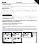
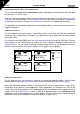
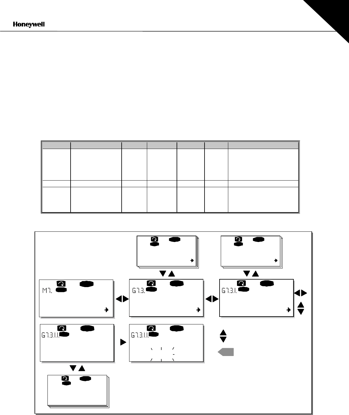
Expander board menu (M7)
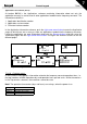
The Expander board menu makes it possible for the user 1) to see what expander boards are
connected to the control board and 2) to reach and edit the parameters associated with the
expander board.
Enter the following menu level
(G#)
with the right arrow menu button At this level, the user can
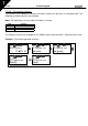
browse through slots (see page 40) A to E with the Browser buttons to see what expander boards
are connected. The lowermost line of the display shows the number of parameters associated with
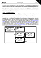
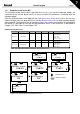
the board. It is possible to view and edit the parameter values in the same way as described in
chapter 7.3.2. See Table 7-9 and Figure 7-25.
Expander board parameters
Code Parameter Min Max Default Cust Selections
P7.1.1.1 AI1 mode 1 5 3
1
=0…20 mA
2
=4…20 mA
3
=0…10 V
4
=2…10 V
5
=–10…+10 V
P7.1.1.2 AI2 mode 1 5 1 See P7.1.1.1
P7.1.1.3 AO1 mode 1 4 1
1
=0…20 mA
2
=4…20 mA
3
=0…10 V
4
=2…10 V
Table 7-9. Expander board parameters (board NXOPTA1)
Figure 7-25. Expander board information menu
G1
"
G5
READY
I/Oterm
C:NXOPTC1
READY
I/Oterm
G1
"
G2
READY
I/Oterm
READY
I/Oterm
enter
P1
"
P4
D:NXOPTC2
READY
I/ Ot er m
G1
"
G2
READY
I/ Ot er m
V1
"
V2
READY
I/Oterm
READY
I/Oterm
Expander boards
Parameters
Slave address
126
CHANGE VALUE
CONFIRM CHANGE
Slave address
126
Baud rate
Auto
Monitor