
- NX series User's Manual POWER SUPPLY
Cabling and connections
43(86)
6
6.2.2
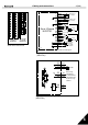
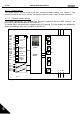
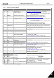
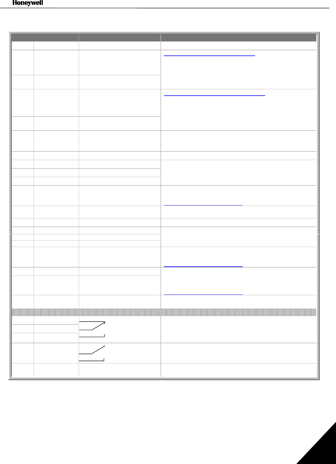
Control terminal signals
Terminal Signal Technical information
1
+10 Vref Reference voltage Maximum current 10 mA
2
AI1+ Analogue input,
voltage or current
Selection V or mA with jumper block X1 (see page 45):
Default: 0– +10V (Ri = 200 k
Ω
)
(-10V…..+10V Joy-stick control, selected with a jumper)
0– 20mA (Ri = 250
Ω
)
3
GND/AI1– Analogue input common Differential input if not connected to ground;
Allows
±
20V differential mode voltage to GND
4
AI2+ Analogue input,
voltage or current
Selection V or mA with jumper block X2 (see page 45):
Default: 0– 20mA (Ri = 250
Ω
)
0– +10V (Ri = 200 k
Ω
)
(-10V…..+10V Joy-stick control, selected with a jumper)
5
GND/AI2– Analogue input common Differential input if not connected to ground;
Allows
±
20V differential mode voltage to GND
6
24 Vout
(bidirectional)
24V auxiliary voltage
±
15%, maximum current 250mA (all boards total);150mA
(from single board); Can also be used as external power
backup for the control unit (and fieldbus)
7
GND I/O ground Ground for reference and controls
8
DIN1 Digital input 1
9
DIN2 Digital input 2
10
DIN3 Digital input 3
R
i
= min. 5k
Ω
11
CMA Digital input common A for
DIN1, DIN2 and DIN3.
Must be connected to GND or 24V of I/O terminal or
to external 24V or GND
Selection with jumper block X3 (see page 45):
12
24 Vout
(bidirectional)
24V auxiliary voltage Same as terminal #6
13
GND I/O ground Same as terminal #7
14
DIB4 Digital input 4
15
DIB5 Digital input 5
16
DIB6 Digital input 6
R
i
= min. 5k
Ω
17
CMB Digital input common B for
DIB4, DIB5 and DIB6
Must be connected to GND or 24V of I/O terminal or
to external 24V or GND
Selection with jumper block X3 (see page 45):
18
AO1+ Analogue signal (+output)
19
AO1– Analogue output common
Output signal range:
Current 0(4)–20mA, R
L
max 500
Ω
or
Voltage 0—10V, R
L
>1k
Ω
Selection with jumper block X6 (see page 45):
20
DO1 Open collector output Maximum U
in
= 48VDC
Maximum current = 50 mA
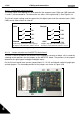
NXOPTA3
21
RO1/1
22
RO1/2
23
RO1/3
Relay output 1 Maximum switching voltage 250VAC, 125VDC
Maximum switching current8A/24VDC,
0.4A/250VDC
Min. switching load 5V/10mA
25
26
RO2/1
RO2/2
Relay output 2 Maximum switching voltage 250VAC, 125VDC
Maximum switching current8A/24VDC, 0.4A/250VDC
Min. switching load 5V/10mA
28
29
TI1/1
TI1/2
Thermistor input 1 Basic galvanic isolation
Double isolation when connected to thermistor
Table 6-5. Control I/O terminal signals