
- NX series User's Manual POWER SUPPLY

40(86)
Cabling and connections
6
6.2 Control unit
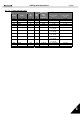
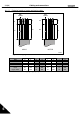
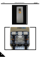
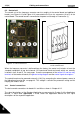
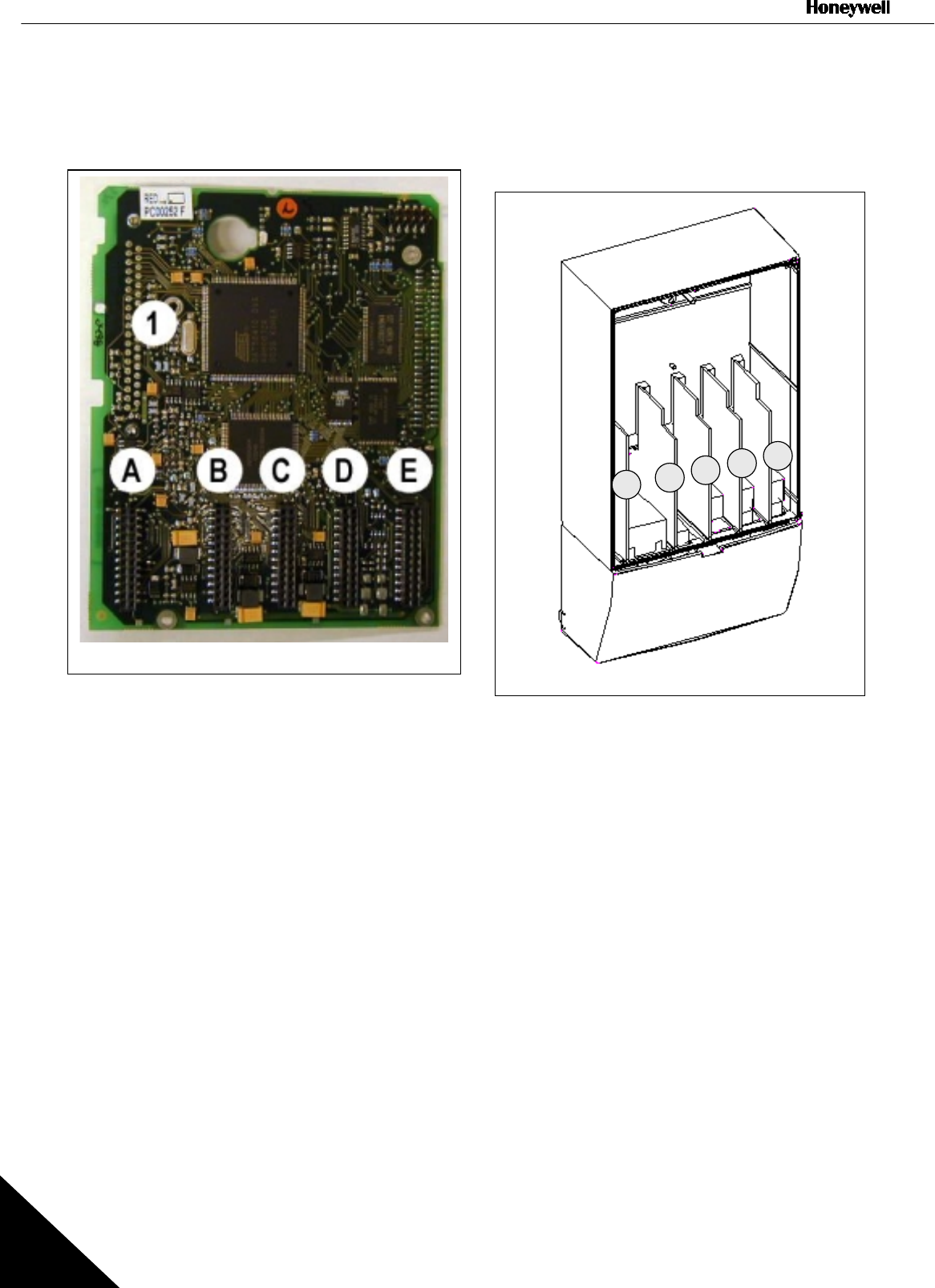
The control unit of the frequency converter consists roughly of the control board and additional
boards (see Figure 6-12 and Figure 6-13) connected to the five slot connectors (A to E) of the
control board. The control board is connected to the power unit through a D-connector (1).
Figure 6-12. NX control board Figure 6-13. Basic and option board connections
on the control board
When the frequency converter is delivered from the factory, the control unit includes at least the
standard compilation of two basic boards (I/O board and thermistor board) which are normally
installed in slots A and B. The next pages show the arrangement of the control I/O and the relay
terminals of the two basic boards, the general wiring diagram and the control signal descriptions.
The control board can be powered externally (+24V) by connecting the external power source to
the bidirectional terminal #6, see page 43. This voltage is sufficient for parameter setting and for
keeping the fieldbus active.
6.2.1
Control connections
The basic control connections for boards A1 and A3 are shown in Chapter 6.2.2.
The signal descriptions of the Standard Application are presented in Chapter 2 of the Application
Manual. If some other
application
is used, check the Application Manual for the signal
descriptions of the respective application.
A
B
C
D
E