
- NX series User's Manual POWER SUPPLY
28(86)
Cabling and connections
6
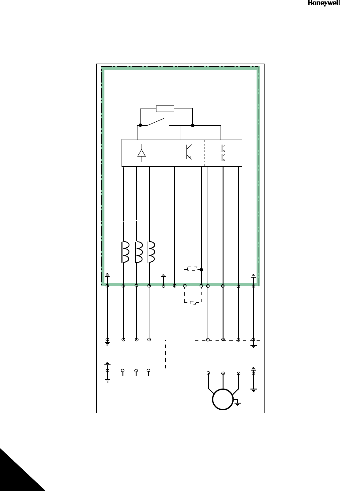
6. CABLING AND CONNECTIONS
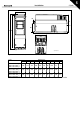
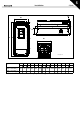
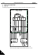
6.1 Power unit
The following wiring diagrams show the mains and motor connections of the frequency converter.
Figure 6-1. Principal wiring diagram of NX5 power unit, FR4 to FR6
*When using 1-phase supply, connect the cables to terminals L1 and L2.
UVWB+
M
3~
L1* L2* L3
L1 L2 L3
nk6_1.fh8
R-
B-
Power board
External
filter
(option)
External
RFI-filter
(option)
BR
BR
(option)