
- NX series User's Manual POWER SUPPLY
Installation
25(86)
5
C
A
NK5_2
A
2
A
2
D
B
A
B
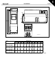
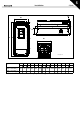
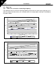
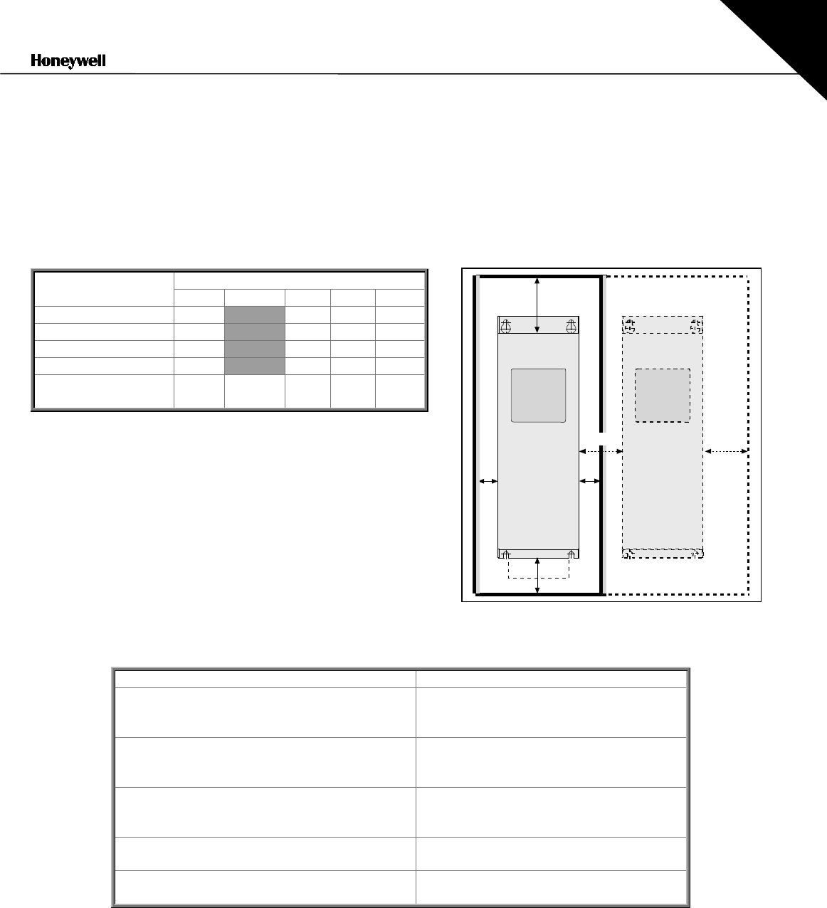
5.2 Cooling
Enough free space should be left around the frequency converter to ensure sufficient air
circulation and cooling. The required dimensions for free space are in the table below.
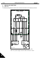
If several units are mounted above each other the required free space equals C + D (see figure
below). Moreover, the outlet air used for cooling by the lower unit must be directed away from the
inlet air to be used by the upper unit.
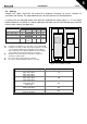
Type Dimensions
A
A
2
BCD
0003—0012 NX_5 20 20 100 50
0016—0031 NX_5 20 20 120 60
0038—0061 NX_5 30 20 160 80
0072—0105 NX_5 80 80 300 100
0140—0205 NX_5 20 200
(150*)
80 300 200
Table 5-6. Mounting space dimensions
Figure 5-6. Installation space
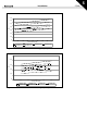
Type Cooling air required
[m
3
/h)
0004—0015 NX_2
0003—0012 NX_5
0005—0019 NX_6
70
0018—0032 NX_2
0016—0031 NX_5
0022—0062 NX_6
190
0048—0078 NX_2
0038—0061 NX_5
0085 NX_6
425
0092—0150 NX_2
0072—0105 NX_5
425
0140—0205 NX_5
0100—0122 NX_6
650
Table 5-7. Required cooling air.
A
= clearance around the freq. converter (see also
A
2
and
B
)
A
2
= clearance needed on either side of the frequency converter
for fan change (without disconneting the motor cables)
*
= min. clearance for fan change (without disconnecting the
motor cables) between two frequency converters
B
= distance from one frequency converter to another or
distance to cabinet wall
C
= free space above the frequency converter
D
= free space underneath the frequency converter