hHoneywell User's Manual NX series Constant and variable torque Variable Speed Drives for induction motors Subject to changes without notice
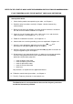
REFER TO THE START-UP QUICK GUIDE BELOWDURING INSTALLATION AND COMMISSIONING. IF ANY PROBLEMS OCCUR, PLEASE CONTACT YOUR LOCAL DISTRIBUTOR. Start-up Quick Guide 1. Check that the product corresponds to your order, see Chapter 3. 2. Read the safety instructions carefully in Chapter 1, before commencing commissioning. 3. Before the mechanical installation, check the minimum clearances around the unit and check the ambient conditions in Chapter 5. 4.
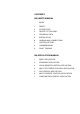
CONTENTS NX USER’S MANUAL INDEX 1 SAFETY 2 EU DIRECTIVE 3 RECEIPT OF DELIVERY 4 TECHNICAL DATA 5 INSTALLATION 6 CABLING AND CONNECTIONS 7 CONTROL KEYPAD 8 COMMISSIONING 9 FAULT TRACING NX APPLICATION MANUAL 1 BASIC APPLICATION 2 STANDARD APPLICATION 3 LOCAL/REMOTE CONTROL APPLICATION 4 MULTI-STEP SPEED CONTROL APPLICATION 5 PID CONTROL APPLICATION 6 MULTI-PURPOSE CONTROL APPLICATION 7 PUMP AND FAN CONTROL APPLICATION
(86) THE NX FREQUENCY CONVERTER USER'S MANUAL AND THE APPLICATION MANUAL The User's Manual will provide the necessary information about the installation, commissioning and operation of NX Frequency Converters. It is recommended that these instructions are studied, before powering up the frequency converter for the first time. The Application Manual provides information about the different applications included in the standard frequency converter.
(86) NX User's Manual Index 1. 1.1 1.2 1.3 1.4 2. 2.1 2.2 2.2.1 2.2.2 2.2.3 2.2.4 3. 3.1 3.2 3.3 3.4 4. 4.1 4.2 4.2.1 4.3 5. 5.1 5.2 5.3 5.3.1 6. SAFETY.................................................................................................................................. 7 WARNINGS ...................................................................................................................................... 7 SAFETY INSTRUCTIONS .....................................................
(86) 6.2.2.2 7. CONTROL KEYPAD ............................................................................................................ 46 7.1 7.1.1 7.1.2 7.1.3 7.1.4 7.2 7.2.1 7.3 7.3.1 7.3.2 7.3.3 7.3.3.1 7.3.3.2 7.3.3.3 7.3.4 7.3.4.1 7.3.4.2 7.3.4.3 7.3.5 7.3.6 7.3.6.1 7.3.6.2 7.3.6.3 7.3.6.4 7.3.6.5 7.3.6.6 7.3.6.7 7.3.6.8 7.3.6.9 7.3.7 7.4 8. 8.1 8.2 9. Jumper selections on the NXOPTA1 basic board .............................................................
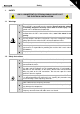
Safety 1. 7(86) SAFETY ONLY A COMPETENT ELECTRICIAN SHOULD CARRY OUT THE ELECTRICAL INSTALLATION 1.1 Warnings 1 2 3 WARNING 4 5 6 The components of the power unit of the frequency converter are live when the NX is connected to mains potential. Contact with this voltage is extremely dangerous and may cause death or severe injury. The control unit is isolated from the potential.
1 8(86) Safety 1.3 Earthing and earth fault protection The NX frequency converter must always be earthed via a conductor connected to the earthing terminal . The earth fault protection inside the frequency converter protects only the converter itself against earth faults in the motor or the motor cable. If fault current protective switches (e.g.
Receipt of delivery 2. 9(86) EU DIRECTIVE 2.1 CE marking The CE marking on the product guarantees the free movement of the product within the EEA (European Economic Area). It also guarantees that the product meets the various requirements defined by the directive. The NX frequency converters carry the CE label as a proof of compliance with the Low Voltage Directive (LVD) and the Electro Magnetic Compatibility (EMC). The company SGS FIMKO has acted as the Competent Body. 2.2 EMC directive 2.2.
(86) Receipt of delivery Class T: The T-class converters have a small earth current and can be used with IT supplies only. If they are used with other supplies no EMC requirements are complied with. Class N: The drives of this class do not provide EMC emission protection. This kind of drives are mounted in enclosures. All NX frequency converters fulfil all EMC immunity requirements (standards EN 50082-1, 50082-2 and EN 61800-3).
Receipt of delivery 11(86) EU DECLARATION OF CONFORMITY We Manufacturer's name: Vacon Oyj Manufacturer's address: P.O.Box 25 Runsorintie 7 FIN-65381 Vaasa Finland hereby declare that the product Product name: NXS Frequency converter Model designation: NXS 0003…. to NXS 0205….
3 Receipt of shipment 12(86) 3. RECEIPT OF SHIPMENT The NX frequency converters have undergone rigorous tests and quality checks at the factory before delivery. However, after unpacking the product, check that no signs of transport damages are to be found on the product and that the delivery is complete (compare the type designation of the product to the code below, Figure 3-1. Should the drive have been damaged during the shipping, contact the carrier and or distributor.
Receipt of shipment 13(86) 3.3 Maintenance In normal conditions, the NX frequency converters are maintenance-free. However, it is recommended the heatsink be cleared periodically with compressed air.The cooling fan can easily be changed if necessary. 3.4 Warranty Only manufacturing defects are covered by the warranty. The manufacturer assumes no responsibility for damages caused during or resulting from transport, receipt of the delivery, installation, commissioning or use.
Technical data 14(86) 4. TECHNICAL DATA 4.1 Introduction Figure 4-1 presents the block diagram of the NX frequency converter. The frequency converter consists of two units, the Power Unit and the Control Unit. The three-phase AC-choke (1) at the mains end together with the DC-link capacitor (2) form an LC-filter, which, again, together with the diode bridge produce the DC-voltage supply to the IGBT Inverter Bridge (3) block.
Technical data 15(86) The control keypad provides a link between the user and the frequency converter. The control keypad is used for parameter setting, reading status data and giving control commands. It is detachable and can be operated externally and connected via a cable to the frequency converter. Also a PC can be used instead of the control keypad, to control the frequency converter, if connected through a similar cable.
Technical data 16(86) 4.2 Power ratings 4.2.1 NX5 – Mains voltage 380—500 V High overload = 200% starting torque, 2 sec/20 sec, 150% overloadability, 1 min/10 min Low overload = 150% starting torque, 2 sec/20 sec, 110% overloadability, 1 min/10 min All sizes up to and including FR8 available with IP21 enclosure and IP54 as option.
Technical data 17(86) 4.3 Technical data Mains connection Motor connection Input voltage Uin 208...240 V; 380...500 V; 525...690 V; -15%...+10% 45...66 Hz Input frequency Once per minute or less (normal case) Connection to mains 0—Uin Output voltage Continuous output current IH: Ambient temperature max. +50ºC, overload 1.5 x IH (1min/10min) IL: Ambient temperature max. +40ºC, overload 1.
(86) EMC Technical data Immunity Emissions Fulfil all EMC immunity requirements EMC level H: EN50082-2, EN61800-3 (1st environment, restricted use; 2nd environment) EN50178, EN60204-1, CE, UL, cUL, FI, GOST R , IEC 61800-5 (see unit nameplate for more detailed approvals) Safety Control connections Analogue input voltage 0...+10V, Ri = 200kΩ, (–10V...+10V joystick control) Resolution 0.
Installation 5. 19(86) INSTALLATION 5.1 Mounting The frequency converter can be mounted in either vertical or horizontal position on the wall or on the back plane of a cubicle. Enough space shall be reserved around the frequency converter in order to ensure a sufficient cooling, see Figure 5-6, Table 5-6 and Table 5-7. For safe installation, ensure that the mounting surface is relatively even. The frequency converter should be fixed with four screws (or bolts, depending on the unit size).
5 20(86) Installation Ø W2 D1 H1 H2 H3 W1 Ø fr5ip21.fh8 Figure 5-1.
Installation 21(86) W2 H4 D1 H5 D2 H1 H2 H3 W1 Ø fr5ip21kaulus.fh8 Figure 5-2. NX dimensions, IP21 with collar, FR4 to FR6 Type 0004—0015 NX_2 0003—0012 NX_5 0005—0019 NX_6 0018—0032 NX_2 0016—0031 NX_5 0022—0035 NX_6 0048—0092 NX_2 0038—0061 NX_5 0042—0085 NX_6 Dimensions H3 H4 H5 D1 D2 ∅ 30 22 190 77 7 419 36 18 214 100 7 558 30 20 237 106 6.5 W1 W2 H1 H2 128 113 337 325 327 144 120 434 420 195 170 560 549 Table 5-2.
5 22(86) Installation H2 Ø W3 W2 W1 H4 H1 H3 fr6aukko.fh8 Figure 5-3. The opening needed for the collar installation, FR4 to FR6 Type 0004—0015 NX_2 0003—0012 NX_5 0005—0019 NX_6 0018—0032 NX_2 0016—0031 NX_5 0022—0035 NX_6 0048—0092 NX_2 0038—0061 NX_5 0042—0085 NX_6 W1 W2 W3 H1 H2 H3 H4 ∅ 123 113 – 315 325 – 5 6.5 135 120 – 410 420 – 5 6.5 185 170 157 539 549 7 5 6.5 Table 5-3.
Installation 23(86) H7 W4 W2 H6 D1 H4 D2 H3 H1 H2 H4 W3 W1 H5 fr7kaulusip21.fh8 Figure 5-4. NX dimensions, IP21 with collar, FR7 and FR8 Type 0120—0150 NX_2 0072—0105 NX_5 0085—0122 NX_6 0140—0205 NX_5 W1 W2 W3 W4 H1 H2 H3 H6 H7 D1 D2 ∅ 237 175 270 253 652 632 630 188.5 188.5 23 20 257 117 5.5 285 – 355 330 832 – 745 57 288 110 9 H4 258 H5 265 43 Table 5-4.
5 24(86) Installation H2 H5 H2 H4 H3 H6 H1 W1 W2 W3 Ø fr7aukko.fh8 Figure 5-5. The opening needed for the collar installation, FR7/FR8 Type 0120—0150 NX_2 0072—0105 NX_5 0085—0122 NX_6 0140—0205 NX_5 W1 W2 W3 H1 H2 H3 H4 H5 H6 ∅ 233 175 253 619 188.5 188.5 34.5 32 7 5.5 301 – 330 810 258 265 – – – 9 Table 5-5.
Installation 25(86) 5.2 Cooling Enough free space should be left around the frequency converter to ensure sufficient air circulation and cooling. The required dimensions for free space are in the table below. If several units are mounted above each other the required free space equals C + D (see figure below). Moreover, the outlet air used for cooling by the lower unit must be directed away from the inlet air to be used by the upper unit.
5 26(86) Installation 5.3 Power loss 5.3.1 Power loss as function of switching frequency If the operator wants to raise the switching frequency of the drive for some reason (typically e.g. in order to reduce the motor noise), this inevitably affects the output power reducing it according to the graphs below.
Installation 27(86) 1400,00 1200,00 1000,00 P [W] 800,00 600,00 400,00 200,00 0,00 0,00 2,00 4,00 6,00 8,00 10,00 12,00 14,00 16,00 Switching frequency [kHz] 0038NX5 400V 0061NX5 400V 0038NX5 500V 0061NX5 500V 0045NX5 400V 0045NX5 500V Figure 5-9.
Cabling and connections 28(86) 6. CABLING AND CONNECTIONS 6.1 Power unit The following wiring diagrams show the mains and motor connections of the frequency converter. Power board BR L1 L2 L3 B- B+ R- U V W BR (option) External RFI-filter (option) External filter (option) L1* L2* L3 nk6_1.fh8 M 3~ Figure 6-1. Principal wiring diagram of NX5 power unit, FR4 to FR6 *When using 1-phase supply, connect the cables to terminals L1 and L2.
Cabling and connections 29(86) Power board L1 L2 L3 B- B+R- U V W BR (option) External RFI-filter (option) External filter (option) L1* L2* L3 nk6_2.fh8 M 3~ Figure 6-2. Principal wiring diagram of NX5 power unit, ≥FR7 *When using 1-phase supply, connect the cables to terminals L1 and L2.
Cabling and connections 30(86) 6.1.1 Power connections Use cables with heat resistance of at least +60°C. The cables and the fuses must be dimensioned according to the frequency converter nominal OUTPUT current which can be found on the rating plate. Dimensioning according to the output current is recommended because the frequency converter input current never significantly exceeds the output current. Installation of cables according to UL regulations is presented in Chapter 6.1.3.
Cabling and connections 6.1.1.4 31(86) Cable and fuse sizes Frame Type IL [A] FR4 FR4 FR5 FR5 FR5 FR6 0003—0009 0012 0016 0022 0031 0038—45 3—9 12 16 22 31 38—45 10 16 20 25 35 50 Mains and motor cable 2 Cu [mm ] 3*1.5+1.5 3*2.5+2.
Cabling and connections 32(86) 6.1.2 Installation instructions 1 2 3 Before starting the installation, check that none of the components of the frequency converter are live. If the frequency converter is installed outside either a switchgear, separate cubicle or electrical room, it must be equipped with a protection cover (see e.g. Figure 6-4) as provided by the regulations for IP21 protection class.
Cabling and connections 5 33(86) Connect the cables: ! Strip the motor and mains cables as advised in Table 6-3 and Figure 6-3. ! Remove the screws of the cable protection plate. ! Make holes into and pass the cables through the rubber grommets on the bottom of the power unit (see e.g. Figure 6-7). ! Connect the mains, motor and control cables into their respective terminals (see e.g. Figure 6-7). ! For information on the installation of larger units, please contact your local distributor.
Cabling and connections 34(86) 6.1.2.1 Stripping lengths of motor and mains cables Earth conductor Earth conductor A1 C1 A2 C2 B1 D1 B2 D2 MAINS MOTOR nk6141.fh8 Figure 6-3. Stripping of cables Frame FR4 FR5 FR6 FR7 FR8 0140 0168—0205 A1 15 20 20 25 B1 35 40 90 120 C1 10 10 15 25 D1 20 30 60 120 A2 7 20 20 25 B2 50 60 90 120 C2 7 10 15 25 D2 35 40 60 120 23 28 240 240 23 28 240 240 23 28 240 240 23 28 240 240 Table 6-3.
Cabling and connections 6.1.2.2 35(86) NX frequency converter frames and installation of cables Note: To connect an external brake resistor, see separate Brake Resistor Manual. See also Chapter Internal brake resistor connection (P6.3.3) on page 69 in this manual. Figure 6-4. NX, FR4 DC-terminals Brake resistor terminals Earth terminals Mains cable Motor cable Figure 6-5.
(86) Cabling and connections Figure 6-6. NX, FR5. Protection class IP21 DC terminals Brake resistor terminals Earth terminals Mains cable Figure 6-7.
Cabling and connections 37(86) Figure 6-8. NX, FR6. Protection class IP21. Brake resistor DC terminals Brake resistor terminals terminals Earth terminals Earth Mains cable Mains cable Motor cable Motor cable Figure 6-9.
(86) Cabling and connections Figure 6-10. NX, FR7. Protection class IP21. Brake resistor DC terminals terminals Earth terminals Mains cable Figure 6-11.
Cabling and connections 6.1.3 39(86) Cable installation and the UL standards To meet the UL (Underwriters Laboratories) regulations, a UL-approved copper cable with a minimum heat-resistance of +60/75°C must be used. The tightening torques of the terminals are given in Table 6-4. Type NX5 0003—0012 NX5 0016—0031 NX5 0038—0061 NX5 0072—0105 NX5 0140 NX5 0168—0205 Frame FR4 FR5 FR6 FR7 FR8 FR8 Tightening torque [Nm] 0.5—0.6 1.2—1.5 4 10 20/9* 40/22* Tightening torque in-lbs.
Cabling and connections 40(86) 6.2 Control unit The control unit of the frequency converter consists roughly of the control board and additional boards (see Figure 6-12 and Figure 6-13) connected to the five slot connectors (A to E) of the control board. The control board is connected to the power unit through a D-connector (1). A Figure 6-12. NX control board B C D E Figure 6-13.
Cabling and connections Basic I/O board NXOPTA1 Board A1 in slot A NXOPTA1 Board A3 in slot B NXOPTA3 Figure 6-14. The I/O terminals of the two basic boards 41(86) 1 +10Vref 2 AI1+ 3 GND 4 AI2+ 5 AI26 24Vout 7 GND 8 DIN1 9 DIN2 10 DIN3 11 CMA 12 24Vout 13 GND 14 DIN4 15 DIN5 16 DIN6 17 CMB 18 AO1+ 19 AO120 DO1 Reference (voltage) Reference (current) 24 V GND 24 V GND 0(4)/20mA RL<500Ω + U<+48V I<50mA nk6_13 Dotted line indicates the connection with inverted signals Figure 6-15.
Cabling and connections 42(86) 6.2.1.1 Control cables The control cables shall be at least 0.5 mm2 screened multicore cables, see Table 6-1. The maximum terminal wire size is 2.5 mm2 for the relay terminals and 1.5 mm2 for other terminals. 6.2.1.2 Galvanic isolation barriers The control connections are isolated from the mains potential and the GND terminals are permanently connected to ground. See Figure 6-17. The digital inputs are galvanically isolated from the I/O ground.
Cabling and connections 6.2.2 1 43(86) Control terminal signals Terminal +10 Vref Signal Reference voltage Technical information Maximum current 10 mA 2 AI1+ Analogue input, voltage or current Selection V or mA with jumper block X1 (see page 45): Default: 0– +10V (Ri = 200 kΩ) (-10V…..
Cabling and connections 44(86) 6.2.2.1 Digital input signal inversions The active signal level depends on which potential the common inputs CMA and CMB (terminals 11 and 17) are connected to. The alternatives are either +24V or ground (0 V). See Figure 6-18. The 24-volt control voltage and the ground for the digital inputs and the common inputs (CMA, CMB) can be either internal or external.
Cabling and connections Jumper block X1: AI1 mode A B C Jumper block X2: AI2 mode D A AI1 mode: 0...20mA; Current input A B C B D C A A B C A D A Jumper block X6: AO1 mode B C D AO1 mode: 0...20mA; Current output A B C D B C D B C D AI2 mode: Voltage input; 0...10V (differential) AI1 mode: Voltage input; -10...10V A C AI2 mode: Voltage input; 0...10V D AI1 mode: Voltage input; 0...10V (differential) B AI2 mode: 0...20mA; Current input AI1 mode: Voltage input; 0...
7 46(86) 7. Control keypad CONTROL KEYPAD The control keypad is the link between the frequency converter and the user. The NX control , keypad features an alphanumeric display with seven indicators for the Run status (RUN, READY, STOP, ALARM, FAULT) and three indicators for the control place (I/O term/ Keypad/BusComm). There are also three Status Indicator LEDs (green - green - red), see Status LEDs (green – green – red) below. The control information, i.e.
Control keypad 47(86) 4 READY = Lights when AC power is on. In case of a trip, the symbol will not light up. 5 ALARM = Indicates that the drive is running outside a certain limit and a warning is given. 6 FAULT = Indicates that unsafe operating conditions were encountered due to which the drive was stopped. Control place indications (See control keypad) 7.1.
7 48(86) 7.1.4 Control keypad Text lines (See control keypad) The three text lines (•, ••, •••) provide the user with information on his present location in the keypad menu structure as well as with information related to the operation of the drive. • •• ••• = Location indication; displays the symbol and number of menu, parameter etc. Example: M3 = Menu 3 (References); R1 = Reference no. 1 (Freq. reference) = Description line; Displays the description of menu, value or fault.
Control keypad 49(86) 7.2 Keypad push-buttons The alphanumeric control keypad features 9 push-buttons that are used for the control of the frequency converter (and motor), parameter setting and value monitoring. Figure 7-2. Keypad push-buttons 7.2.1 Button descriptions reset = This button is used to reset active faults (see Chapter 7.3.4). select = This button is used to switch between two latest displays. May be useful to see how the changed new value influences some other value.
7 50(86) Control keypad start = Start button. Pressing this button starts the motor if the keypad is the active control place. See Chapter 7.3.3.1. stop = Stop button. Pressing this button stops the motor (unless disabled by parameter R3.4/R3.6). 7.3 Navigation on the control keypad The data on the control keypad are arranged in menus and submenus. The menus are used for example for the display and editing of measurement and control signals, parameter settings (chapter 7.3.
Control keypad READY R EADY I/Oterm R EADY I/Ote rm Expander boards G1"G5 STOP I/Oterm A:NXOPTC1 Parameters G1"G1 R EADY STOP I/Ote rm System Menu S1"S9 Standard Browse READY I/Ote rm READY I/Ote rm Fault history H1"H3 I/Oterm 11 Output phase T1"T7 FAULT STOP I/Ote rm Active faults F0 R EADY STOP I/O Terminal Browse Change value RUN READY L oc al Basic parameters P1"P15 I/Ote rm Monitor 17 R EADY I/Ote rm R EADY Operation days enter Control Place R EADY FAULT
7 52(86) 7.3.1 Control keypad Monitoring menu (M1) The monitoring menu can be entered from the main menu by pushing the Right arrow menu button when the location indication M1 is visible on the first line of the display. How to browse through the monitored values is presented in Figure 7-4. The monitored signals carry the indication V#.# and they are listed in Table 7-1. The values are updated once every 0.3 seconds. This menu is only for signal checking. The values cannot be altered here.
Control keypad 7.3.2 53(86) Parameter menu (M2) Parameters are the way of conveying the commands of the user to the frequency converter. The parameter values can be edited by entering the Parameter Menu from the Main Menu when the location indication M2 is visible on the first line of the display. The value editing procedure is presented in Figure 7-5. Push the right arrow menu button once to move into the Parameter Group Menu (G#).
7 54(86) Control keypad Parameter lock (P6.3.2)). Return to the Main menu anytime by pressing the left arrow menu button for 1—2 seconds. The basic application package includes seven applications with different sets of parameters. The parameter lists are in the Application Section of this manual. Once in the last parameter of a parameter group, To move directly to the first parameter of that group press the Browser button up. See the diagram for parameter value change procedure on page 55.
Control keypad 55(86) READY Ke ypa d Input signals P1"P8 READY READY Keypad Keypad Parameters G1 "G8 Basic parameters P1 "P18 READY READY Keypad Keypad Min Frequency 13.95 Hz Min Frequency enter 14.45 Hz Figure 7-5.
7 56(86) 7.3.3 Control keypad Keypad control menu (M3) In the Keypad Controls Menu, it is possible to choose the control place, edit the frequency reference and change the direction of the motor. Enter the submenu level with the right arrow menu button. NOTE! There are some special functions that can be performed when in the M3 menu: start Select the keypad as the active control place by keeping the button pushed down for 3 seconds when the motor is running.
Control keypad STOP READY STOP I /Oterm READY I/ Oterm Keypad control P1"P3 Control Place I/O Remote I/O Remote STOP READY Keypad STOP I/ Oterm Control Place STOP I/ Oterm Control Place 57(86) READY K eypad enter Control Place Keypad Figure 7-6. Selection of control place 7.3.3.2 Keypad reference The keypad reference submenu (P3.2) displays and allows the operator to edit the frequency reference. The changes will take place immediately.
7 58(86) 7.3.4 Control keypad Active faults menu (M4) The Active faults menu can be entered from the Main menu by pushing the right arrow menu button when the location indication M4 is visible on the first line of the keypad display. When a fault brings the frequency converter to a stop, the location indication F1, the fault code, a short description of the fault and the fault type symbol (see Chapter 7.3.4.1) will appear on the display.
Control keypad Fault type symbol A (Alarm) F (Fault) AR (Fault Autoreset) FT (Fault Trip) Table 7-2. Fault types Meaning This type of fault is a sign of an unusual operating condition. It does not cause the drive to stop, nor does it require any special actions. The 'A fault' remains in the display for about 30 seconds. An 'F fault' is a kind of fault that makes the drive stop. Actions need to be taken in order to restart the drive. If an 'AR fault' occurs the drive will also stop immediately.
7 60(86) 7.3.4.2 Control keypad Fault codes The fault codes, their causes and corrective actions are presented in the table below. The shadowed faults are A faults only. The faults written in white on black background may appear as both A and F fault. Fault code 1 Overcurrent 2 Overvoltage 3 Earth fault 5 Charging switch 6 Emergency stop 7 Saturation trip 8 System fault The frequency converter troubleshooting system is unable to locate the fault.
Control keypad Fault code 16 Fault Possible cause Correcting measures Motor overtemperature Motor overheating has been detected by frequency converter motor temperature model. Motor is overloaded. Motor underload protection has tripped. Parameter save fault − faulty operation − component failure Changes may have occurred in the different counter data due to mains interruption − faulty operation − component failure Decrease the motor load.
7 62(86) 7.3.4.3 Control keypad Fault time data record When a fault occurs the information described above in 7.3.4 is displayed. By pushing the right #T.13. arrow menu button it is possible to view the Fault time data record menu indicated by T.1# In this menu, some selected important data valid at the time of the fault are recorded. This feature is intended to help the user or the service person to determine the cause of fault.
Control keypad 7.3.5 63(86) Fault history menu (M5) The Fault history menu can be entered from the Main menu by pushing the right arrow menu button Menu button right when the location indication M5 is visible on the first line of the keypad display. All faults are stored in the Fault history menu, Browse through them using the Browser buttons. Additionally, the Fault time data record pages (see Chapter 7.3.4.3) are accessible at each fault.
7 64(86) 7.3.6 Control keypad System menu (M6) The System menu can be entered from the main menu by pushing the right arrow menu button Menu button right when the location indication M6 is visible on the display. The controls associated with the general use of the frequency converter, such as application selection, customised parameter sets or information about the hardware and software are located under the System menu.
Control keypad 65(86) Functions in the System menu Code Function S6.1 Application selection Basic Application S6.2 Language selection English S6.3.1 Password P6.3.2 Parameter lock Not used Change Enabled P6.3.3 Internal brake resistor Connected P6.3.4 Fan control Continuous P6.3.5 Multimonitoring page Change enabled P6.3.6 P6.3.7 P6.4.1 P6.4.2 P6.4.3 P6.4.4 P6.4.5 S6.5.1 S6.5.2 HMI acknowledg.
7 66(86) Control keypad Code D6.7.6.1.3 C6.8.1 C6.8.2 C6.8.3 T6.9.1 T6.9.2 T6.9.3 T6.9.4 T6.9.5 Function Info: Applications: Firmware interface MWh counter Operating days counter Operating hours counter MWh trip counter Clear MWh trip counter Operating days trip counter Operating hours trip counter Clear operating time counter Min Table 7-5.
Control keypad 7.3.6.1 67(86) Application selection The user can select the application desired by entering the Application selection page (S6.1). This is done by pushing the right arrow menu button when on the first page of the System menu. Change the application by pushing the right arrow menu button once again. The name of the application starts to blink. Browse through the applications with the Browser buttons and select another application with the Enter button.
7 68(86) Control keypad READY READY I/Oterm I/O term Language System Menu S1"S11 English READY READY I/Oterm I/Oterm Language enter Language Suomi English Figure 7-10. Selection of language 7.3.6.3 System settings In the System settings submenu (S6.3) under the System menu it is possible to further customise the frequency converter operator interface.
Control keypad 69(86) Parameter lock (P6.3.2) This function allows the user to prohibit changes to the parameters. If the parameter lock is activated the text *locked* will appear on the display when the parameter value is edited. NOTE: This function does not prevent unauthorised editing of parameter values. Enter the edit mode by pushing the right arrow menu button HYPERLINK \l "menubuttonright". Use the Browser buttons to change the parameter lock status.
7 70(86) Control keypad READY READY I/Oterm I/Oterm I/Oterm System settings P1"P7 System Menu S1"S9 READY InternBrakeRes Connected READY I/Oterm I/Oterm InternBrakeRes enter InternBrakeRes Not conn. Connected Figure 7-13. Internal brake resistor connection Fan control (P6.3.4) This function allows the control of the frequency converter’s cooling fan. When the power is switched on the fan can be set to run continuously or dependant on the temperature of the unit.
Control keypad 71(86) Example: • • • Transfer delay between the frequency converter and the PC = 600 ms The value of par. 6.3.6 is set to 1200 ms (2 x 600, sending delay + receiving delay) The corresponding setting shall be entered to the [Misc]-part of the NCDrive.ini – file: Retries = 5 AckTimeOut = 1200 TimeOut = 6000 It must also be considered that intervals that are shorter than the AckTimeOut-time cannot be used in NCDrive monitoring. Enter the edit mode by pushing the right arrow menu button.
7 72(86) Control keypad READY READY I/O term I/Oterm Default page Keypad settings P1 "P5 0. Figure 7-16. Keypad settings submenu Default page (P6.4.1) This menu allows the user to set the location (page) to which the display automatically moves as the Timeout time (see below) has expired or as the power is switched on to the keypad. If the Default Page value is 0 the function is not activated, i.e. the last displayed page remains on the keypad display.
Control keypad 73(86) Contrast adjustment (P6.4.4) In case the display is unclear adjust the contrast through the same procedure as that for the timeout time setting (see above). Backlight time (P6.4.5) Giving a value for the Backlight time, can determine how long the backlight stays on before going out. Select here any time between 1 and 65535 minutes or 'Forever'. For the value setting procedure see Timeout time (P6.4.3). 7.3.6.
7 74(86) Control keypad Download parameters to drive (From keypad, S6.5.2) This function downloads one or all parameter groups uploaded to the keypad to a drive provided that the drive is in STOP status. Enter the From keypad page (S6.5.2) from the Parameter copy menu. Push the right arrow menu button to enter the edit mode. Use the Browser buttons to select either the option All parameters or Application parameters and press the Enter button. Wait until 'OK' appears on the display.
Control keypad 75(86) If the user wants the parameters of the new application to be automatically uploaded to the keypad this will have to be done for the parameters of the new application once on page 6.5.1 as instructed. Otherwise the panel will always ask for the permission to upload the parameters. Note: Parameters saved in the parameter settings on page S6.5.
7 76(86) 7.3.6.7 Control keypad Information submenu In the Information submenu (S6.7) frequency converter-related hardware and software information as well as operation-related information, can be found. Enter the Info menu by pressing the right arrow menu button. The user can now browse through the information pages with the Browser buttons. Page 6.7.1 6.7.2 6.7.3 6.7.4 6.7.5 6.7.6 6.7.
Control keypad 77(86) Applications info submenu (S6.7.6) At location S6.7.6 is the Applications submenu containing information about not only the application currently in use but also all other applications loaded into the frequency converter. The information available is: 1. Application identification number 2. Application version number 3.
7 78(86) 7.3.6.9 Control keypad Trip counters submenu Trip counters (menu S6.9) are counters the values of which can be reset i.e. restored to zero. The following resettable counters are available: Note! The trip counters run only when the motor is running. Page T6.9.1. T6.9.3. T6.9.4. Counter MWh counter Operation day counter Operation hour counter Table 7-8. Resettable counters The counters can be reset on pages 6.9.2. (MWh counter reset) and 6.9.5. (Operation time reset).
Control keypad 7.3.7 79(86) Expander board menu (M7) The Expander board menu makes it possible for the user 1) to see what expander boards are connected to the control board and 2) to reach and edit the parameters associated with the expander board. Enter the following menu level (G#) with the right arrow menu button At this level, the user can browse through slots (see page 40) A to E with the Browser buttons to see what expander boards are connected.
7 80(86) Control keypad 7.4 Further keypad functions The NX control keypad embodies additional application-related functions. See the NX Application Package for more information.
Commissioning 8. 81(86) COMMISSIONING 8.1 Safety Before commissioning, note the following directions and warnings: 1 2 3 4 5 WARNING 6 Internal components and circuit boards of the frequency converter (except for the galvanically isolated I/O terminals) are live when the NX is connected to mains potential. Coming into contact with this voltage is extremely dangerous and may cause death or severe injury.
Commissioning 82(86) 7 Set the parameters of group 1 (See the Application Manual) according to the requirements of the application. At least the following parameters should be set: - motor nominal voltage motor nominal frequency motor nominal speed motor nominal current The values needed for the parameters are on the motor rating plate. 8 Perform run test without motor Perform either Test A or Test B: A Controls from the I/O terminals: a) Turn the Start/Stop switch to ON position.
Commissioning 83(86) 10 Connect the motor to the process (if the startup test was run without the motor being connected) a) Before running the tests, make sure that this can be done safely. b) Inform co-workers of the tests. c) Repeat test 8A or 8B.
9 84(86) 9. Fault tracing FAULT TRACING When a fault is detected by the frequency converter control electronics, the drive is stopped and the symbol F together with the ordinal number of the fault, the fault code and a short fault description appear on the display. The fault can be reset with the Reset button on the control keypad or via the I/O terminal. The faults are stored in the Fault history menu (M5) which can be browsed. The different fault codes can be found in the table below.
Fault tracing 14 Frequency converter over temperature 15 16 Motor stalled Motor overtemperature 17 22 23 Motor underload EEPROM checksum fault 24 Changed data warning 25 Microprocessor watchdog fault 32 Fan cooling 34 36 CAN bus communication Control unit 37 Device change 38 Device added 39 Device removed 40 41 Device unknown IGBT temperature 42 Brake resistor overtemperature Encoder fault 43 50 51 52 Analogue input Iin < 4mA (selected signal range 4 to 20 mA) External fault Keyp
Austria Honeywell Austria Ges.m.b.H. Handelskai 388 1023 Wien Phone: (43) 1 72 78 00 Fax: (43) 1 72 78 08 www.honeywell.at Italy Honeywell S.p.A. Via Gobetti, 2b 20063 Cernusco sul Naviglio Phone: (39) 02 92 14 61 Fax: (39) 02 92 1468 88 www.honeywell.it Switzerland Honeywell AG Honeywell-Platz 1 8157 Dielsdorf Phone: (41) 18 55 24 24 Fax: (41) 18 55 24 25 www.honeywell.ch Belgium Honeywell S.A. 3, avenue du Bourget 1140 Bruxelles Phone: (32) 27 28 27 11 Fax: (32) 27 28 24 68 Netherlands Honeywell B.V.