
User's Manual

NV-EC1701 NV-EC1701
Model NV-EC1701
www.nvt.com ● (+1) 650.462.8100 ● (+44) (0) 208 977 6614
Ethernet over Coax Transceiver
Model NV-EC1701
www.nvt.com ● (+1) 650.462.8100 ● (+44) (0) 208 977 6614
Ethernet over Coax Transceiver
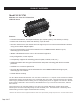
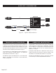
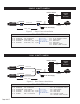
DVR / NVR
Hybrid DVR
or
NVR
Monitor
LAN/WAN
48VDC Power Supply
IP Camera
6 Watt
≤1,800 ft (550 m)
RG 59/U 20AWG
Cat5
≤328ft
(≤100m)
INSTALLATION INSTRUCTIONS
Figure 1 - Typical Installation
MULTIPLE CAMERAS
PoE CONSIDERATIONS
Most installations that use the NV-EC1701 transceiver involve the
replacement of an analog camera with an IP camera, while reusing the
installed coax cable. Since most IP cameras support PoE (Power over
Ethernet), the legacy 24VAC distribution may no longer be needed.
Disconnect all analog equipment from the coax before installing the
IP equipment. The NV-EC1701 uses the coax to deliver 48V DC. To
prevent damage, never connect analog cameras or analog control-room
equipment to an NV-EC1701.
Transceiver Configuration
NVT EoC transceivers must be configured to communicate exclusively
with other transceivers within their Network Group. The configura-
tion process is described on page 3.
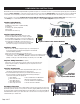
Connecting the Camera End
Install the new IP camera. Mount the NV-EC1701 nearby. Connect the
enclosed grey RJ45 patch cable between the network connector (PoE)
of the camera and the RJ45 jack on the NV-EC1701. Connect the coax
to the BNC jack on the NV-EC1701.
For most installations, the IP camera power will be low enough, and the
coax distance short enough, so that the IP camera and its NV-EC1701
can receive power through the coax. In most cases, a power supply will
not be needed at this end. For additional details, see “High Power
Extended Distance Considerations” on page 7.
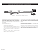
Connecting the Control-room End
Install a second NV-EC1701 at the control-room end of the coax cable.
If rack-mounting is desired, use the NV-RMEC16 tray, which supports
up to four NV-EC1701 transceivers, which together can support up to 16
cameras.
Connect the coax cable to the BNC jack on the NV-EC1701.
Connect a class 2 (SELV) 48VDC power supply to the jack labeled
“48VDC” on the NV-EC1701.
This will provide power to the entire system, including the cameras. The
Blue “Power” LEDs will illuminate on both transceivers.
Connect the enclosed red RJ45 patch-cord between the RJ45 jack on
the NV-EC1701 and either: 1) an IP camera video input on a Hybrid DVR,
or 2) an Ethernet switch allocated for video. See “Hybrid DVR Consider-
ations” on page 5, or “NVR Considerations” on page 6.
The Green LEDs will illuminate when a network link is established, and
will blink when data traffic is present.
For rev B and B1 transceivers, the 48V is “always on.” Use the enclosed
red RJ45 patch cord to connect to control-room hubs or non-PoE equip-
ment.
NVT’s Class 2 current limiting ensures safety of the installation during
fault conditions, while delivering higher power (up to 45 watts) with
more efficient allocation amongst loads.
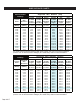
Unlike conventional PoE, voltage-drop and load current must be
confirmed by the installer. See “High Power Extended Distance Consid-
erations” on page 7.
!
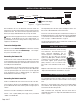
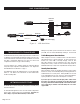
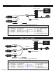
The NV-EC1701 communicates via the coax using
a bus-architecture. This means that up to four
remote camera-end NV-EC1701s may be
connected together to a fifth NV-EC1701 at the
control-room. The coax cables are connected
together using BNC splitters, available from NVT,
or elsewhere. If you purchase BNC “T” connectors
from another supplier, please purchase high
quality connectors. Low cost connectors have
been found to have intermittent shield connec-
tions.
Multiple IP cameras draw more current. To ensure adequate power, see
“High Power Extended Distance Considerations” on page 7.
Page 4 of 17
Cat5
≤328ft
(≤100m)
NV-BNCT
NV-EC4BNC