
User's Manual

CONFIGURATION INSTRUCTIONS
Page 3 of 17
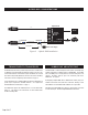
NV-EC1701 EoC transceivers transmit high bandwidth encrypted Ethernet signals over conventional coax cables. To provide utmost signal integrity and security, NVT EoC
transceivers must be configured to communicate exclusively with other transceivers within their Network Group. This group typically consists of one NV-EC1701
located at the control room (usually connected to an ethernet switch or router), and up to four remote NV-EC1701 transceivers (usually connected to IP cameras).
Before connecting to the network, each NV-EC1701 must learn which other NV-EC1701 transceivers are to be part of that group. This simple process is
called Joining. It is recommended that transceivers in each Network Group be configured prior to deployment using these instructions:
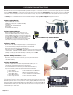
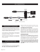
Step One: Gather Materials
● Up to five NV-EC1701 transceivers
● 48VDC power supply & line-cord (NV-PS48-60W)
● Coax jumper
● Small paper-clip, partially straightened
● Device labels
● IP Network Documentation Log
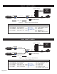
Step Two: Connect Hardware
● Remove and discard the “Configure Before Use” labels.
● Connect two NV-EC1701 transceivers using a coax jumper.
● Connect 48VDC power supply to one transceiver; Apply power.
● Verify that the blue POWER LED on each transceiver illuminates.
● Verify that the green BNC LED on each transceiver is off.
If a BNC LED is on, the transceiver has been previously joined.
Perform the un-joining process below before proceeding.
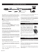
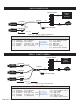
Step Three: Joining
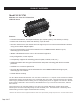
● On one transceiver, using the straightened paper-clip, momentarily depress
the small push-button located behind and slightly above the RJ45 LED.
The RJ45 LED will begin blinking.
● Depress the same push-button on the second transceiver.
● Both transceivers are now in Join Mode. They will find each other and establish encrypted
communication. In about 10 seconds, the BNC LEDs on both transceivers will illuminate
(blinking or steady on), and the RJ45 LED will go off, indicating a successful Join.
Step Four: Adding Transceivers (if required)
● Disconnect one of the transceivers and replace it with a new un-joined transceiver.
● Repeat steps two and three to add additional (up to five total) transceivers to the
same Network Group.
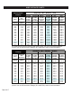
Step Five: Documentation
● Label the configured transceivers with a unique Network Group ID of your choice.
This will help you identify them after they have been deployed.
● Record this Network Group information in your IP Network Documentation Log.
This log may include essential documentation which will help you identify all
system devices during and after deployment:
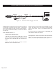
Un-Joining a Transceiver
If you need to move a transceiver from one Network Group to another, it must first un-learn its previous
Network Group and be returned to an un-joined state. Do this by applying 48VDC power, and pressing
the small push-button located behind and slightly above the RJ45 LED for four seconds until the BNC and
RJ45 LEDs illuminate and then go out, about 10 seconds. The transceiver is now ready to be joined to a
new Network Group, as outlined above.
Power
Step Five: Transceiver MAC Address
Step Three:
transparent view
of push-button location
Step One: Gather Materials
Step Two: Remove Label; Connect Hardware
●
Camera Number
●
Camera Position/Location
●
Camera Make & Model
●
Camera MAC & IP Address
●
Camera Login & Password
●
Camera-end NVT Transceiver MAC Address
●
NVT Transceiver Network Group Name
●
Control Room NVT Transceiver MAC Address
●
Control Room Router Port Number