
Corp. Computer Hardware User Manual

Tegra 200 Series Developer Board User Guide
DG-04927-001_v01 Advance Information – Subject to Change 27
NVIDIA CONFIDENTIAL
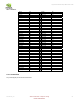
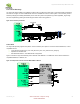
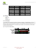
Table 9. PCIe Pinout
Signal Pin
Signal Pin
PEX_CLK_OUT1_N AC4 PEX_L1_TXN AC2
PEX_CLK_OUT1_P AD4 PEX_L1_TXP AC1
PEX_CLK_OUT2_N Y4 PEX_L2_RXN V4
PEX_CLK_OUT2_P Y5 PEX_L2_RXP V3
PEX_L0_RXN AA5 PEX_L2_TXN AA1
PEX_L0_RXP AA4 PEX_L2_TXP AA2
PEX_L0_TXN AD1 PEX_L3_RXN V6
PEX_L0_TXP AD2 PEX_L3_RXP V5
PEX_L1_RXN AA7 PEX_L3_TXN Y3
PEX_L1_RXP AA6 PEX_L3_TXP Y2
4.6 Display
LCD Displays
HDMI
VGA (CRT)
SDTV / HDTV Out
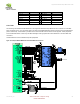
4.6.1 LCD Displays
The Tegra 250 supports a broad range of interfaces for connecting to LCD displays. Two separate display controllers can drive
up to two displays. One of the displays can be an LCD while the other an HDMI display, standard NTSC/PAL TV or CRT.
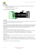
Alternately, a number of dual LCD combinations are supported. An 18-bit interface to an external LVDS Transmitter to connect
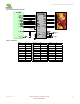
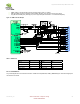
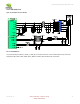
to common Smartbook panels is described. Other interface options are possible. The example assumes an SPWG 18BPP
single channel LVDS panel interface.
Figure 15. Single Channel LVDS Signal Mapping