
Corp. Computer Hardware User Manual

Tegra 200 Series Developer Board User Guide
DG-04927-001_v01 Advance Information – Subject to Change 21
NVIDIA CONFIDENTIAL
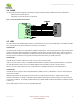
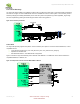
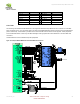
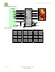
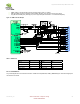
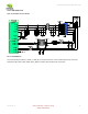
Figure 9. Crystal Connection Example
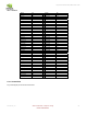
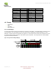
Table 6 Crystal and Circuit Requirements
Symbol Parameter Min Typ Max Unit
F
P
Parallel resonance crystal Frequency 12 MHz
F
TOL
Frequency Tolerance ±50 ppm
C
L
Load Capacitance for crystal parallel resonance 5 7 10 pf
DL Crystal Drive Level 300 uW
R
BIAS
External Bias Resistor 2 MΩ
ESR Equivalent Series Resistance 80 Ω
Note:
FP, FTOL, CL and DL are found in the Xtal Datasheet
ESR = RM * (1 + C0/CL)/2 where RM = Motional Resistance, C0 =Shunt Capacitance from Xtal datasheet.
Datasheets may specify ESR directly – consult manufacturer if unclear whether ESR or RM are specified.
Load capacitor values (C
Lx
) can be found with formula C
L
= [(C
L1
xC
L2
)/(C
L1
+C
L2
)]+C
PCB
Or since C
L1
and C
L2
are typically of equal value, C
L
= (C
Lx
/2)+C
PCB
. or C
Lx
= (C
L
– C
PCB
) x 2
CL = Load capacitance (Xtal datasheet). CPCB is PCB capacitance (trace, via, pad, etc.)