Socket AM3 Processor Mainboard User’s Manual Rev: 1.
Disclaimer The intellectual property of this manual belongs to our company. The ownership of all of the products, including accessories and software etc. belong to our company. No one is permitted to copy, change, or translate without our written permission. We compiled this manual based on our careful attitude, but we can not guarantee the accuracy of the contents.
Table of Contents Chapter 1 Introduction ....................................................................... 3 1.1 Package Checklist .............................................................................................. 3 1.2 Specifications ..................................................................................................... 4 1.3 Mainboard Layout .............................................................................................. 5 1.
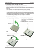
nVIDIA MCP61 Series User's Manual Chapter 1 Introduction 1.1 Package Checklist Thank you for choosing our product. Please check the following packing and accessories, if there is any broken or part missing, please contact with your franchiser.
nVIDIA MCP61 Series User's Manual 1.
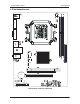
nVIDIA MCP61 Series User's Manual 1.3 Mainboard Layout JC61D3C01 V1 .
nVIDIA MCP61 Series User's Manual 1.4 Connecting Rear Panel I/O Devices The rear I/O part of this mainboard provides the following I/O ports: (optional) • PS/2 Mouse: Connects to a PS/2 mouse. • PS/2 Keyboard: Connects to a PS/2 keyboard. • VGA: Connects to a monitor's VGA input. • COM: Connect to external modem.mouse or other devices that support this communication portocol. • LAN: The LAN port allows the motherboard to connect to a local area network by means of a network hub.
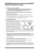
nVIDIA MCP61 Series User's Manual Chapter 2 Hardware Setup 2.1 Choosing a Computer Chassis The mainboard and its component layouts illustrated in this chapter were based mainly on model “nVIDIA MCP61”, unless specifically stated. • Choose a chassis big enough to install this mainboard. • As some features for this mainboard are implemented by cabling connectors on the mainboard to indicators and switches or buttons on the chassis, make sure your chassis supports all the features required.
nVIDIA MCP61 Series User's Manual 2.3 Installation of the CPU and CPU Cooler Before installing the CPU, please comply with the following conditions: 1. Please make sure that the mainboard supports the CPU. 2. Please take note of the one indented corner of the CPU. If you install the CPU in the wrong direction, the CPU will not insert properly. If this occurs, please change the insert direction of the CPU. 3. Please add an even layer of heat sink paste between the CPU and CPU cooler. 4.
nVIDIA MCP61 Series User's Manual 2.3.2 Installation of the CPU Cooler For proper installation, please kindly refer to the instruction manuals of your CPU Cooler. 2.4 Installation of Memory Modules This mainboard provides two 1.5v DDR3 DIMM slots, which supports dual channel memory technology. To activate the dual channel configuration, you need to install two identical (same brand, speed, size and chip-type) memory modules into these DIMM slots.
nVIDIA MCP61 Series User's Manual 2.5 Connecting Peripheral Devices 2.5.1 Floppy and IDE Disk Drive Connectors JC61D3C01 V1 . 1 170 * 235 COM Each of the IDE port connects up to two IDE drives at Ultra ATA 66/100/133 mode by one 40-pin, 80-conductor,and 3-connector Ultra ATA/66 ribbon cables.
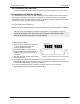
nVIDIA MCP61 Series User's Manual Chapter 3 Jumpers & Headers Setup 3.1 Checking Jumper Settings • For a 2-pin jumper, plug the jumper cap on both pins will make it CLOSE (SHORT). Remove the jumper cap, or plug it on either pin (reserved for future use) will leave it at OPEN position. • For 3-pin jumper, pin 1~2 or pin 2~3 can be shorted by plugging the jumper cap in. How to identify the PIN1 jumpers? Please check the mainboard carefully, the PIN1 is marked by "1" or white thick line. 3.
nVIDIA MCP61 Series User's Manual 3.4 FAN Power Connectors These connectors each provide power to the cooling fans installed in your system. CFAN: CPU Fan Power Connector SFAN1: System Fan Power Connector JC61D3C01 V1 . 1 170 * 235 COM 3 VGA These fan connectors are not jumpers. DO NOT place jumper caps on these connectors. BAT JLAN LPT FUSB2 3.5 Front Panel Switches & SPEAKER Headers JC61D3C01 V1 .
nVIDIA MCP61 Series User's Manual 3.6 Additional USB Port Headers JC61D3C01 V1 . 1 170 * 235 COM 3 VGA Pin Pin Assignment Pin Pin Assignment 1 3 VCC Data 0- 2 4 VCC Data 1- 5 Data 0+ 6 Data 1+ 7 Ground 8 10 Ground NC BAT JLAN LPT FUSB2 3.7 Front Panel Audio Connection Header This header provides the connection to audio connector at front panel. JC61D3C01 V1 . 1 170 * 235 COM 3 VGA BAT JLAN LPT FUSB2 Pin No.
nVIDIA MCP61 Series User's Manual 3.8 S/PDIF Output Connection Header S/PDIF (Sony/Philips Digital Interface) is a standard audio transfer file format. It is usually found on digital audio equipment such as a DAT (Digital Audio Tape) machine or audio processing device. It allows the transfer of audio from one file to another without the conversion to and from an analog format, which could degrade the signal quality. JC61D3C01 V1 .
nVIDIA MCP61 Series User's Manual 3.9 Power Connectors ATXPWR (ATX Power) connector We recommend to use our motherboard with a power supply that complies with the ATX12V Power Supply Design Guide Version 1.1. Every ATX12V power supply unit has a standard 24-pin ATX main power connector that must be plugged into this connector. If you would like to use an old power supply with only a 20-pin ATX main power connector, then please plug the 20-pin ATX main power connector along with pin 1 and pin 13.
nVIDIA MCP61 Series User's Manual Chapter 4 BIOS Setup Utility BIOS stands for Basic Input and Output System. It was once called ROM BIOS when it was stored in a Read-Only Memory (ROM) chip. Now manufacturers would like to store BIOS in EEPROM which means Electrically Erasable Programmable Memory. BIOS used in this series of mainboard is stored in EEPROM, and is the first program to run when you turn on your computer. BIOS performs the following functions: 1.
nVIDIA MCP61 Series User's Manual 4.5 BIOS Setup — CMOS Setup Utility • In order to increase system stability and performance, our engineering staff is constantly improving the BIOS menu. The BIOS setup screens and descriptions illustrated in this manual are for your reference only, and may not completely match with what you see on your screen. • Do not change the BIOS parameters unless you fully understand its function. 4.5.
nVIDIA MCP61 Series User's Manual 4.5.
nVIDIA MCP61 Series User's Manual • Language Allows you to selects the current default language used by the BIOS. • Floppy A Allows you to selects the type of floppy disk drive installed in your system. If you do not install a floppy disk drive, set this item to None. Options are: None, 360K/5.25", 1.2M/5.25", 720K/3.5",1.44M/3.5", 2.88M/3.5".
nVIDIA MCP61 Series User's Manual 4.5.4 Advanced Setting Main Advanced Boot BIOS SETUP UTILITY Security Power JUSTw00T! Advanced Settings Configure CPU. WARNING: Setting wrong values in below sections may cause system to malfunction. ► ► ► ► Exit ← Select Screen Select Item Enter Go to Sub Screen F1 General Help F10 Save and Exit ESC Exit CPU Configuration Chipset Onboard Device PCIPnP ↑ ↓ v02.61 (C)Copyright 1985-2006, American Megatrends, Inc.
nVIDIA MCP61 Series User's Manual ► Chipset Click key to enter its submenu. BIOS SETUP UTILITY Advanced Advanced Chipset Setting WARNING: Setting wrong values in below sections may cause system to malfunction. Options PCI Express->PCI-> IGP->PCI->PCI Expr Options NUMM ROM Version: 4.082.
nVIDIA MCP61 Series User's Manual ► Onboard Device Configuration Click key to enter its submenu.
nVIDIA MCP61 Series User's Manual • Legacy USB Support Enabled or Disabled Legacy USB option, and Auto option disables legacy support if no USB devices are connected. • USB 2.0 Controller Mode Allow you to selects the HiSpeed(480Mbps) or FullSpeed(12Mbps). • BIOS EHCI Hand-Off This is a workaround for OSes without EHCI hand-off support. The EHCI ownership change should claim by EHCI driver. ・Press key to return to "Onboard Device Configuration" menu.
nVIDIA MCP61 Series User's Manual BIOS SETUP UTILITY Advanced Advanced PCI/PnP Settings WARNING: Setting wrong values in below sections may cause system to malfunction.
nVIDIA MCP61 Series User's Manual • OffBoard PCI/ISA IDE Card This item works for most PCI IDE cards, some PCI IDE cards may require this to be set to the PCI slot number that is holding the card. Optional:Auto,PCI Slot1~6 4.5.5 Boot Setting Main Advanced Boot BIOS SETUP UTILITY Security Power JUSTw00T! Boot Settings Exit Configure Settings during System Boot.
nVIDIA MCP61 Series User's Manual 4.5.6 Security Setting Main Advanced Boot BIOS SETUP UTILITY Security Power JUSTw00T! Security Settings Supervisor Password : Not Installed User Password : Not Installed Exit Install or Change the password. ← Select Screen Select Item Enter Change F1 General Help F10 Save and Exit ESC Exit ↑ ↓ Change Supervisor Password Change User Password BIOS Sector Virus Protection [Disabled] v02.61 (C)Copyright 1985-2006, American Megatrends, Inc.
nVIDIA MCP61 Series User's Manual BIOS SETUP UTILITY Power ACPI Configuration ACPI Aware O/S Suspend mode ACPI Version Festures ACPI APCI support Select the ACPI state used for System Suspend. [Yes] [S1 (POS)] [ACPI V1.0] [Enabled] ← ↑ ↓ +F1 F10 ESC Select Screen Select Item Change Option General Help Save and Exit Exit v02.61 (C)Copyright 1985-2006, American Megatrends, Inc.
nVIDIA MCP61 Series User's Manual • Resume On PCIE Wake# Disable/Enable PCIE PME to generate a wake event. • Resume On LAN(MAC) Disable/Enable LAN(MAC) to generate a wake event. • Resume On Ring Disable/Enable RI to generate a wake event. • Resume On USB options:Disabled,Enabled • Resume By RTC Alarm When set to [Enabled], you can set the date and time you would like the Soft-Off PC to power-on in the “RTC Alarm Date (Days)” and “System Time” items.
nVIDIA MCP61 Series User's Manual • CPUFAN Mode Setting Available options: Manual Mode,Thermal Cruise Mode,Speed Cruise Mode • CPUFAN PWM Control According to PWM out configuration adjustable CPU Fan speed. 4.5.
nVIDIA MCP61 Series User's Manual • Bank Interleaving Sets the bank interleaving feature. • Channel Interleaving Enable Channel Memory Interleaving. • Enable Clock to All DIMMs This item is to enable or disable the unused clocks to DIMMs even the memory slots are not populated. • MemClk Tristate C3/ATLVID Enables or disables the MemClk Tri-Stating during C3 and Alt VID. • Memory Hole Remapping Enables or disables the memory remapping around the memory hole.
nVIDIA MCP61 Series User's Manual ► AMD Overclocking Configuration Click key to enter its submenu. BIOS SETUP UTILITY JUSTw00T! AMD Overclocking Configuration Speed:2727MHZ, NB Clk:2000MHZ Maximum FSB Multiplier :13.
nVIDIA MCP61 Series User's Manual 4.5.9 Exit Options Main Advanced BIOS SETUP UTILITY Security Power JUSTw00t! Boot Exit Options Exit Exit system setup after saving the changes. Save Changes and Exit Discard Changes and Exit Discard Changes F10 key can be used for this operation. Load Optimal Defaults Load Failsafe Defaults ← Select Screen Select Item Enter Go to Sub Screen F1 General Help F10 Save and Exit ESC Exit ↑ ↓ v02.61 (C)Copyright 1985-2006, American Megatrends, Inc.
nVIDIA MCP61 Series User's Manual Discard Changes and Exit Highlight this item and select ,then press to discard any changes that you have made in the Setup Utility and exit the Setup Utility. Or press to return to the main menu. BIOS SETUP UTILITY Main Advanced Boot Security Power JUSTw00t! Exit Exit Options Exit system setup without saving any changes. Save Changes and Exit Discard Changes and Exit Discard Changes ESC key can be used for this operation.
nVIDIA MCP61 Series User's Manual Load Optimized Defaults This option opens a dialog box that let you install optimized defaults for all appropriate items in the Setup Utility. Select and then to install the defaults. select and then to not install the defaults. The optimized defaults place demand on the system that may be greater than the performance level of the components, such as the CPU and the memory.
nVIDIA MCP61 Series User's Manual Chapter 5 Driver Installation Check your package and there is Driver CD included. This CD consists of all drivers you need. In addition, this CD also include an auto detect software which can tell you which hardware is installed, and which drivers needed so that your system can function properly. Insert CD into your CD-ROM drive and the menu should appear as below.
nVIDIA MCP61 Series User's Manual When you choose Mainboard Driver installation Utility, the drivers menu should appear as below: Back <- nForce Chipset Installation Utility Nvidia VGA Graphics Driver Onboard LAN Driver Realtek HD Audio Driver Exit (This picture is only for reference) From the Drivers MENU you may make 5 selections: 1. nForce Chipset Installation Utility 2. Nvidia VGA Graphics Driver 3. Onboard LAN Driver 4. Realtek HD Audio Driver 5. Exit: Click to exit this installation menu.