
Phau Ntawv Qhia

nVent.com/RAYCHEM | 3
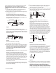
3. Attach the tee assembly to the near end of the water supply
pipe, per local codes. Be sure the tee is installed so that the
cable will be able to pass straight through the tee and into
the pipe with no bending required (see Figure 6).
Figure 6
4. Attach structure supply pipe to the tee opening as shown in
Figure 6, per local codes, using appropriate materials. If the
cable will be installed as in Figure 8 and a shutoff valve will be
used in this section of the pipe, the total length of unheated
pipe (pipe plus valve without cable in it) must not exceed 6 in
(150 mm).
Note: Do not position the pipe in which the heating cable
will be inserted in such a way as to cause sharp bends in
the pipe.
Note: If this installation is for pipe supplying water to a
manufactured home, the structure supply connection
should be made underneath the vapor barrier supplied with
the home, if possible (see Figure 8).
5. If the cable is being installed in new pipe, follow Step 5a; if
being installed in existing pipe, follow Step 5b.
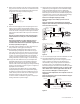
5a. Ensure adaptor and appropriate pipe fittings to accept
threaded coupling are properly connected to the tee, per
local codes, and fully insert the cable into the water supply
pipe through remaining opening in tee assembly as shown
in Figure 7 or Figure 8 as appropriate for the installation. If
a valve or shutoff is installed at any point on the pipe, the
heating cable must not pass through it. Proceed to Step 6.
5b. If no pipe has been added to the tee, ensure adaptor and
appropriate pipe fittings to accept threaded coupling are
properly connected to the tee, per local codes, and fully
insert the cable into the water supply pipe through remaining
opening in tee assembly as shown in Figure 7 or Figure 8 as
appropriate for the installation.
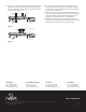
If a length of pipe was added to the tee, ensure adaptor
and appropriate pipe fittings to accept threaded coupling
are properly connected to end of the ‘added pipe’ per local
codes, and fully insert the cable into the water supply pipe
through the end of the pipe as shown in Figure 9.
If a valve or shutoff is installed at any point on the pipe, the
heating cable must not pass through it.
Structure
supply pipe
Near end of
water supply pipe
Outside
wall
6. Wrap several turns of Teflon tape around the tapered thread
(exposed end) of the supplied 1/2 in NPT threaded coupling.
Fasten the threaded coupling to the tee or ‘added pipe’
assembly. Ensure compression nut is not tight and push the
brass fitting into the back end of the threaded coupling until it
stops (about 3/4 in (19 mm) of the coupling will be showing).
Tighten the compression nut onto the brass fitting.
Note: Do not overtighten coupling assembly.
Note: Do not plug in the assembly to power source at
this time.
Note: The total length of unheated pipe from the pitless
adaptor or outer well casing to the end of the heating cable
must not exceed 3 in (75 mm).
Figure 7
Figure 8
7. Turn on water supply to pipe and check installation for leaks.
8. Fully extend temperature sensor cord and attach
temperature sensor to pipe as shown in Figure 7 (for thru
walls) or Figure 8 (for under floors) as appropriate for
the installation, using tie-wraps provided. If installation is
as shown in Figure 7, the temperature sensor MUST be
attached to the pipe as far from the outside wall as possible.
Note: Do not attach temperature sensor to a section of pipe
that is indoors or to a section of pipe where water will not
flow, such as the ‘added pipe’ as shown in Figure 9.
Note: Do not leave temperature sensor exposed to sense air
temperature.
Note: The temperature sensor must be attached to the pipe
before insulating the pipe.
Figure 9
Pitless
adaptor
Ouside
wall
Structure
supply pipe
To water supply
Well
casing
3 in max
(75 mm)
Temperature sensor Compression nut
Brass fitting
Threaded
coupling
Pitless adaptor
Structure supply pipe
To water supply
Well
casing
3 in max
(75 mm)
6 in max
(150 mm)
Temperature sensor Compression nut
Brass fitting
Threaded
coupling
Floor or
vapor barrier
To structureOutside
wall
water system
Threaded
coupling
Added pipe attached to tee
Adaptor to accept
1/2 in threaded coupling