
Installation Manual

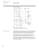
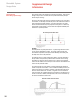


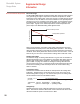
Table Of Contents

Electrical Design
The ElectroMelt EM2-XR self-regulating heating cable varies its power output at
every point along its length in response to the surface temperature or sheath
temperature of the heating cable. When the concrete in contact with the surface
of the heater is cool, the cable is cool and the resistance of the specially blend-
ed polymer core is low, resulting in high power output. As the pavement warms,
the heating cable core warms and the core resistance rises, resulting in lower
power output. A graph of the relationship between sheath temperature and
power output of the EM2-XR heating cable appears below.
During normal operation, the heating-cable output varies between the points
marked "Maximum Startup Power" and "Steady-State Operation." The heating-
cable operating temperature varies with the concrete temperature and weather
conditions, but is usually about 60ºF warmer than the concrete surface. On a hot
summer day, the concrete in contact with the heating cable could reach 150ºF.
Startup Temperature
The maximum length of heating cable allowed on a given size circuit breaker is
determined primarily by the current drawn by the heating cable during low-tem-
perature (high-power) startup conditions. The maximum circuit length data
given in Table 1 on page 12 is based on starting the heating cable when the
concrete pavement is at 0ºF. A maximum length circuit started at 0ºF will result
in branch circuit loading of less than 80 percent of the circuit breaker rating
within 10 minutes.
Transformer Sizing
Transformers should be sized to handle the startup load of the heating cable
indefinitely. To determine the current load of each circuit, refer to the circuit
breaker rating tables on page 12. The actual current per foot of heating cable
and the transformer size are calculated as follows:
Current Circuit breaker rating
per foot Maximum allowed length of heating cable at design voltage
Transformer Current Total Heating Heating Cable
size per foot cable length operating voltage
Voltage Drop
Calculate the branch circuit voltage drop based on the current as computed
above. Note that the maximum size branch circuit conductor that can be termi-
nated in the EMK-XP power connection kit is 4 AWG.
20
ElectroMelt System
Design Guide
Supplemental Design
Information
0.8 x
x
x
=
=
Electrical Performance Requirements
Maximum Startup Power
Steady State Operation
Heating Cable Sheath Temperature ( F)
0 275
P
o
we
r (
w
at
ts
/f
o
ot
)