
Installation Manual

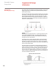


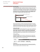
Table Of Contents

18
ElectroMelt System
Design Guide
Supplemental Design
Information
Using Figures 1-6
Once you have determined the correct curve to use for your application, turn to
the correct figure for that curve and take the following steps:
1. Draw a horizontal line across the figure at the heating-cable spacing you
plan to use in the design.
2. Draw vertical lines from the points where the segmented snow melting per-
performance curves intersect your horizontal heating-cable-spacing line.
3. From the intersection of the left vertical line with the percentage axis read the
percentage of all snowfall conditions for which the pavement will be com-
pletely clear.
The distance between the left and right vertical lines is the additional percent-
age of all snowfall conditions for which the pavement may have a light snow
cover. The distance, if any, from the right line to the end of the percentage axis
is the percentage of snowfall conditions for which snow may actually accumu-
late while the system is in operation. If increased snow-melting performance is
required, reduce the heating cable spacing.
Example
To determine the snow-melting performance you should specify for ElectroMelt
heating cable installed on 10-inch centers in Chicago, Illinois, find the figure
number for Chicago in Table 4. The table refers you to Figure 1.
Using Figure 1, you see that the intersection of the 10-inch spacing line with the
"Surface Completely Clear" curve occurs at approximately 88%, and the inter-
section with the "Some Accumulation Possible" curve occurs at 0%
These percentages indicate that the system with 10-inch spacing will keep the
surface completely clear for 88% of all snowfall conditions occurring in Chicago,
and will allow no accumulation.
For the remaining 12% of conditions, the surface may have a light covering of
snow, but the system will be able to melt snow at the same rate at which it falls
(no accumulation).