
Installation Manual

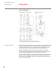


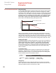
Table Of Contents

14
ElectroMelt System
Design Guide
Design Steps
Installation and Testing
Typical Control Diagram
Supplied Power 480 V/277 3 , 4 wire
1
2
3
Control Power 120 Vac
N*
GFPD
TraceGuard 277
50 A
100 A
E 104
100 A/Pole,
120 V
Power Connection
Kit EMK-XP
ElectroMelt Cable
with Braid
End Seal Kit
(part of EMK-XP)
100 A
100 A
MCB
Contactor**
Snow
Sensor
15 A
Up to
2000 Ft.
Off Delay Timer
0.5-5.0 Hr
20 A
20 A
Automatic Snow
Controller
SD-CIT-1
(120 V @ 50 W
* Neutral wire must pass through TraceGuard 277 (see Illustration Instructions).
** In 208-volt and 240-volt systems, means should be provided to disconnect both phases.
After the design is completed, the system should be installed and tested. Follow
all design, installation, assembly, and test instructions to ensure proper opera-
tion and to prevent shock or fire. Use only Raychem ElectroMelt connection
components and follow the installation instructions included with them.
Install the ElectroMelt system in accordance with Raychem's ElectroMelt
System installation and Operation Manual (H53392) and the installation instruc-
tions (APP-910B) supplied with the heating cable and components.
Test the insulation resistance of the ElectroMelt heating cable with a 2500-Vdc
Megger. Test after installation, during the concrete pour, and annually there-
after. Refer to the ElectroMelt Installation and Operation Manual (H53392) for
the proper testing procedure.