
Installation Manual
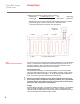

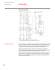


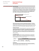
Table Of Contents

Calculate the total length of heating cable required as:
Total heating Heated area (ft²) x 12 end component
cable length Heated cable spacing (in.) allowancesª allowances
ªEnd allowance is the length of heating cable installed between the heated
area and the power connection junction box, measured in feet.
Component allowances measured in feet (see page 8).
This section will help you determine the electrical parameters for an ElectroMelt
system. To determine the demands an ElectroMelt system will place on your
electrical equipment, refer to "Electrical Performance Requirements" in the
Supplemental Design Information section of this guide.
Electrical Protection
The installation and design of the ElectroMelt System is governed by Article
426 of the National Electrical Code. Your installation must also comply with all
applicable local codes and standards. To comply with the National Electrical
Code, use a 30-mA ground-fault protection device (GFPD).
Warning: To minimize the danger of fire from sustained electrical arcing
if the heating cable is damaged or improperly installed, use a ground-fault
protection device with a 30-mA trip level. Electrical fault currents may be
too small to trip conventional circuit breakers.
Voltage
Standard design information is provided for operation at 208 Vac. The allowable
range of voltage for EM2-XR is 208 to 277Vac. Using a voltage higher than
208 volts results in slightly higher surface temperatures and allows longer maxi-
mum circuit lengths as indicated in Tables 1 and 2.
11
ElectroMelt System
Design Guide
Design Steps
Step 3.
Determine Electrical Parameters
=
+
+
b
b
6" (S/2)
12" (S)
6" (S/2)
Junction Box
EMK-XJB
1" Conduit
6"
S = Heating cable spacing