
Installation Manual

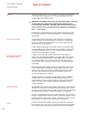
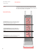


Table Of Contents

For most standard applications, ElectroMelt EM2-XR heating cable may be
installed on 12-inch centers. The design steps that follow are based on 12-inch
spacing.
Snowfall and icing conditions vary widely with location. For this reason, heating
cable installed on 12-inch centers may not provide adequate performance for
every location.
To determine correct heating-cable spacing for a particular location, consult the
Supplemental Design Information section of this guide.
For uniform heating, arrange the heating cable in a serpentine pattern that covers
the area. Space the cable on 12-inch centers or use alternate spacing determined
by consulting the Supplemental Design Information section of this guide.
Maintain the heating cable spacing in the design within 1 inch.
Use these symbols to indicate the heating cable and components:
Power Connection
End Seal
Splice
Do not route the heating cable closer than 4 inches to the edge of the pave-
ment, drains, anchors, or other material in the concrete.
The water resulting from the melted snow or ice should run into a drain or off to
a safe area.
Arrange the heating cable so that both ends of the cable terminate in an above-
ground, UL Listed or CSA Certified weatherproof junction box. The following are
guidelines for this procedure:
• Mount the heating-cable junction box above grade to prevent water entry
Use an EMK-XJB or equivalent UL Listed or CSA Certified weatherproof
junction box.
• Protect the heating cable from the pavement to the junction box by installing
heating cable inside individual 1-inch rigid metal conduits. Minimize the
length of the protective conduit. Do not penetrate building walls or floors with
the protective conduit or insulate the conduit.
• Extend the conduit approximately 6 inches into the concrete for support.
• Provide bushings on both ends of each conduit.
• Do not install more than one run of heating cable per conduit.
• Minimize the length of the conduit.
• Do not insulate the conduit.
• Do not penetrate building floors or walls with the conduit.
If possible avoid crossing expansion, crack-control, or other pavement joints.
Where crossing a joint is unavoidable, use the EMK-XEJ expansion joint kit to
protect the heating cable.
Use these symbols to indicate the location of the joints:
Expansion Joint
Crack-control joint
Expansion joint kit
10
ElectroMelt System
Design Guide
Design Steps
Step 1.
Determine Heating-Cable Spacing
Step 2.
Lay Out Heating Cable