Raychem ElectroMelt System ™ D E S I G N G U I D E
ElectroMelt System Design Guide THIS PAGE LEFT BLANK INTENTIONALLY 2
ElectroMelt System Guide Design Introduction ElectroMelt Products ElectroMelt System Design Design Steps Table of Contents Overview 5 How to Use This Guide 5 How to Use the Installation and Operation Manual 5 System Description 5 Codes 5 Warranty 6 Raychem Self-Regulating Heating Cable Technology 6 Self-Regulating Heating Cable 7 Components 7 Accessories 7 Basic ElectroMelt System Design 9 Design for Standard Applications 9 Design for Nonstandard Applications 9 Step 1.
ElectroMelt System Design Guide THIS PAGE LEFT BLANK INTENTIONALLY 4
ElectroMelt System Design Guide Overview Table of Contents This guide presents Raychem's recommendations for designing and ElectroMelt snow-melting and anti-icing system for use in concrete pavement. Do not use the ElectroMelt system buried in asphalt. WARNING: ElectroMelt heating cable and associated system components are electrical devices that must be designed and installed properly.
ElectroMelt System Design Guide Warranty Introduction The instructions in this guide and in the product packages must be followed. The Raychem warranty will not apply in the event of damage caused by accident, misuse, neglect, alteration, or improper installation, repair, or testing. For the complete warranty statement refer to Appendix A. Raychem Self-Regulating Heating-Cable Technology At low temperature, there are many conducting paths, resulting in high output and rapid pavement heat-up.
ElectroMelt System Design Guide Self-Regulating Heating Cable ElectroMelt Products The ElectroMelt EM2-XR heating cable is embedded in concrete pavement to melt snow and ice that might otherwise accumulate on the surface. The heating cable responds to the local concrete temperature, increasing output when concrete temperature drops and decreasing heat output when concrete temperature rises.
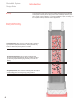
Introduction ElectroMelt System Design Guide Snow Sensor and Controller SD-CIT-1 (optional) Power Connection and End Seal EMK-XP Heating Cable Splice EMK-XS 8 Expansion Joint Kit EMK-XEJ Component Catalog # Usage Power connection kit (includes end seal) Splice kit Expansion joint kit EMK-XP EMK-XS EMK-XEJ One per circuit As required One per expansion joint crossing Heating cable allowance Cable ties EMK-CT One per foot of cable used — Snow controller (optional) SD-CIT-1 One per system —
ElectroMelt System Design Guide Supplemental Design Information Basic ElectroMelt System Design The power produced by ElectroMelt EM2-XR heating cable installed on 12-inch centers is adequate for the majority of concrete-pavement snow-melting and anti-icing systems. For this reason, the design steps in the next section and information in other ElectroMelt literature are based on this spacing.
ElectroMelt System Design Guide Step 1. Determine Heating-Cable Spacing Design Steps For most standard applications, ElectroMelt EM2-XR heating cable may be installed on 12-inch centers. The design steps that follow are based on 12-inch spacing. Snowfall and icing conditions vary widely with location. For this reason, heating cable installed on 12-inch centers may not provide adequate performance for every location.
ElectroMelt System Design Guide Design Steps Calculate the total length of heating cable required as: Total heating = Heated area (ft²) x 12 + componentb + end cable length Heated cable spacing (in.) allowancesª allowances ªEnd allowance is the length of heating cable installed between the heated area and the power connection junction box, measured in feet. b Component allowances measured in feet (see page 8). Junction Box EMK-XJB 6" (S/2) 6" (S/2) Step 3.
ElectroMelt System Design Guide Design Steps Circuit Breaker Rating Use thermal-magnetic circuit breakers rated no greater than 50 amperes for overcurrent protection. Use the lowest rated circuit breaker compatible with the circuit lengths to be used. Use Tables 1 or 2 below to determine maximum circuit length. Table 1.
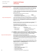
ElectroMelt System Design Guide Design Steps Controls Three control methods are commonly used with snow-melting and anti-icing systems. All three methods require a contactor as shown in the diagram on the next page. The contactor must be sized to carry the load. Each method offers a tradeoff of initial cost against energy efficiency. Choose the one the best meets the project performance and requirements.
ElectroMelt System Design Guide Design Steps Typical Control Diagram Supplied Power 480 V/277 3 , 4 wire 1 2 Control Power 120 Vac 3 N* Snow Sensor MCB 50 A 15 A Up to 2000 Ft. GFPD TraceGuard 277 Off Delay Timer Contactor** 100 A 100 A 100 A 0.5-5.
ElectroMelt System Design Guide Factors Affecting Snow Melting System Design Supplemental Design Information Snow-melting systems are installed for convenience and safety. They are often thought of only in terms of snowfall, but an important-and often the principalfunction may be anti-icing. Anti-icing is the ability of the system to prevent the formation of ice on the pavement surface; it is the ability to maintain all points on the surface above 32°F for given temperature and wind conditions.
ElectroMelt System Design Guide Supplemental Design Information Icing Virtually any level of power will melt snow if there is a sufficiently deep snow cover to insulate the surface from convection-heat loss. However, icing problems may arise once the insulating blanket has been melted and the pavement is subject to increased heat loss due to wind action on the exposed surface.
Supplemental Design Information ElectroMelt System Design Guide Table 3. Ambient Temperatures (°F) for Ice-Free Surfaces Snow Melting Performance Requirements Heating-cable spacing (in inches) Average wind speed during freezing periods 5 mph 10 mph 15 mph 20 mph 6 -40 -25 -10 0 8 -40 -10 0 10 10 -25 0 10 15 12 -15 5 15 20 Obtaining Snowfall Data Snowfall data is not available for all cities.
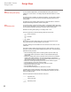
ElectroMelt System Design Guide Supplemental Design Information Using Figures 1-6 Once you have determined the correct curve to use for your application, turn to the correct figure for that curve and take the following steps: 1. Draw a horizontal line across the figure at the heating-cable spacing you plan to use in the design. 2. Draw vertical lines from the points where the segmented snow melting perperformance curves intersect your horizontal heating-cable-spacing line. 3.
Supplemental Design Information ElectroMelt System Design Guide Figure 1. Figure 2. Heating Cable Spacing (inches) 6 6 Surface Completely Clear Surface Completely Clear 8 8 10 10 12 12 Light Cover Possible Light Cover Possible Snow Accumulates 0 50 25 75 Cumulative Snowfall Hours (%) 100 0 Heating Cable Spacing (inches) Figure 3. 25 50 75 Cumulative Snowfall Hours (%) Figure 4.
ElectroMelt System Design Guide Supplemental Design Information Electrical Performance Requirements Electrical Design The ElectroMelt EM2-XR self-regulating heating cable varies its power output at every point along its length in response to the surface temperature or sheath temperature of the heating cable. When the concrete in contact with the surface of the heater is cool, the cable is cool and the resistance of the specially blended polymer core is low, resulting in high power output.
ElectroMelt System Design Guide Supplemental Design Information Example An application at a parking garage requires four heating cable circuits 275 feet long. The heating cable is to be powered at 277 Vac. Circuit Breaker Sizing From Table 1 on page 12, up to 300 feet of heating cable may be connected to a single 50-amp branch circuit breaker. Transformer Sizing The branch circuit current after startup at 0ºF is calculated as follows: 21 Current = 80% x 50 amp/300 ft = 0.
ElectroMelt System Design Guide THIS PAGE LEFT BLANK INTENTIONALLY 22
ElectroMelt System Design Guide Design Steps Project Data Project or area name Submitted by Reference Date Design Data Site Location Minimum ambient temperature Average wind speed Heating cable spacing Description of performance requirements Pavement Data Pavement material Pavement thickness Heating cable depth Type of reinforcement Description of area to be to be heated Is pavement placed on grade? (if not, please describe) Product Data Heating cable model Heating cable manufacturer Product approvals
ElectroMelt System Design Guide THIS PAGE LEFT BLANK INTENTIONALLY 24
ElectroMelt System Design Guide Self-Regulating Heating Cable For Concrete Snow-Melting and Anti-Icing Applications EM2-XR 0.310" 0.700" Description The ElectroMelt EM2-XR heating cable is a high-powered, self-regulating heating cable for concrete snow-melting and anti-icing applications. The uniquely blended polymer core of the heating cable adjusts its power output at every point along its length to eliminate hot spots and burnouts that can be experienced with constant-wattage heating cables.
ElectroMelt System Design Guide Power Connection and End Seal Kit, and Splice Kit For Use with EM2-XR Self-Regulating Heating Cable EMK-XP EMK-XS 6" Power Connection EMK-XP 6" End Seal EMK-XP 10" Splice EMK-XS Description Specifications The ElectroMelt termination and splicing components are used to terminate the end of the heating cable to power conductors or to splice one length of heating cable to another.
ElectroMelt System Design Guide Description Expansion Joint Kit For Use with EM2-XR Self-Regulating Heating Cable EMK-XEJ The ElectroMelt EMK-XEJ expansion joint kit provides physical protection for the heating cable beneath slab joints. An expansion tube is used to form an expansion loop for the heating cable. Specifications Temperature rating 195ºF Storage temperature -40ºF to 140ºF Min.
ElectroMelt System Design Guide Description EMK-XJB Junction Box For Use with EM2-XR Self-Regulating Heating Cable The EMK-XJB is a large, UL Listed weatherproof enclosure suitable for terminating both ends of one EM2-XR circuit. The enclosure is made of molded structural foam and provides high impact strength, excellent chemical resistance, high dielectric strength, and excellent weathering capabilities. It is suitable for outdoor applications.
ElectroMelt System Design Guide Description Specifications SD-CIT-1 Automatic Snow Controller For Use with EM2-XR Self-Regulating Heating Cable The ElectroMelt snow controller features a single snow sensor and a control panel to automatically control the operation of heating cables. The sensor detects snow as precipitation occurs at temperatures below 38°F. The panel provides an adjustable hold-on timer, which allows the heating cable to continue to operate even after snow stops.
ElectroMelt System Design Guide Description Specifications TraceGuard 277™ Ground-Fault Protection Device (GFPD) For Use with EM2-XR Self-Regulating Heating Cable The TraceGuard 277 GFPD (Square D EHB-EPD) is a single-pole, thermalmagnetic circuit breaker with equipment ground-fault protection. The GFPD is rated for use with 480/277-Vac heat-tracing systems with a maximum load of 40 A.
ElectroMelt System Design Guide Description E104 Contactor For USe with EM2-XR Self-Regulating Heating Cable The E104 is a three-pole contactor housed in a thermoplastic enclosure that is lightweight, dusttight, watertight, and corrosion resistant.
ElectroMelt System Design Guide Description Specifications Ordering Information 32 AMC-1A Ambient Sensing Thermostat For Use with EM2-XR Self-Regulating Heating Cable The AMC-1A thermostat responds to air temperature changes detected by a stainless steel sensing probe. The AMC-1A can be used to control a contactor coil.
ElectroMelt System Design Guide Description FH-2616A-1, EMK-CT, EMK-XT, EMK-MARK Accessories For Use with EM2-XR Self-Regulating Heating Cable The ElectroMelt product line has the accessories necessary for a complete installation of EM2-XR cable. The propane torch (FH-2616A-1) is suitable for heat-shrinking the connection kits. The crimping tool (EMK-XT) is the correct size for the crimps in the connection kits. The cable ties (EMK-CT) are 7-inch nylon industrial cable ties.
ElectroMelt System Design Guide EMK-MEG Description The EMK-MEG is a precision instrument that tests the insulation resistance of heating cables. Battery operated and portable for field use, it features a pushto-read and lock-on button to conserve the battery. The Megger can test insulation resistance at voltages up to 5000 Vdc and has neon scale-selection indicators. The kit includes batteries, two test leads, probes, an operation manual and leather carrying case.
ElectroMelt System Design Guide Description EMK-XJR Jacket Repair Kit For Use with EM2-XR Self-Regulating Heating Cable The ElectroMelt jacket repair kit is a wraparound sleeve for covering a damaged outer jacket. The repair sleeve is adhesive-lined and comes with a metal closure channel.
ElectroMelt System Design Guide THIS PAGE LEFT BLANK INTENTIONALLY 36
ElectroMelt System Design Guide Condensed Specification Guide This is the product portion of a specification for the ElectroMelt System. For a complete specification that includes installation and testing recommendations, contact your Raychem representative. PART 1 - GENERAL Furnish and install a UL Listed and CSA Certified snow-melting system complete with heating cable, termination components, junction boxes, contactors, and controls. PART 2 - PRODUCTS 2.
ElectroMelt System Design Guide THIS PAGE LEFT BLANK INTENTIONALLY 38
ElectroMelt System Design Guide Warranty; Suitablity Appendix A (a) Raychem warrants products delivered hereunder against faulty workmanship and use of defective materials for a period of eighteen (18) months from the date of installation or twenty-four (24) months from the date of shipment, whichever is sooner.
TraceGuard and ShrinkWrap are trademarks of Raychem Corporation. Megger is a trademark of Avo Biddle Instruments. ElectroMelt and RayChem are registered trademarks of Raychem Corporation. O R ® Listed 877Z De-Icing and SnowMelting Equipment DESIG. 1B, 2B Raychem Corporation Construction Products Group 40 All of the above information, including illustrations, is believed to be reliable. Users, however, should independently evaluate the suitability of each product for their application.