
Installation Manual


9
SECTION
FLOOR
HEATING
SYSTEM
Nuheat Cable
INSTALLATION
Nuheat Cable Installation Guide
INSTALLATION: PLANNING
2.11 INSTALLATION LAYOUT PLAN CONT...
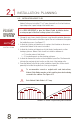
6. Draw the cable runs on the Installation Layout Plan. See Figure 2.16.
7. Duringinstallation,additional“StabilizingCableGuides”mustbeinsertedat3’
(
ft
)
to 4’
(
ft
)
intervals. Determine the location of these additional guides and draw
them on the Installation Layout Plan. See Figure 2.16.
8. Predictingwherethecablewillendisdifcult.Assuch,it’simportanttoinclude
a “Buffer Zone” in the Installation Layout Plan; an area where heating is not
essential(e.g.behindthetoilet,behindadoor,oranyotherlowtrafcarea).
This “Buffer Zone” can be used to accommodate any excess cable or remain
unheated if cable is needed elsewhere. See Figure 2.16.
Identify a “Buffer Zone” on the Installation Layout Plan.
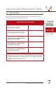
Conduct insulation and resistance tests and record the resistance
readings on page 7.
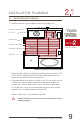
FIGURE 2.16: Installation Layout Plan Example
Thermostat
Perimeter Cable Guides
HeatingCable
Cold Lead
StabilizingCableGuides
Buffer Zone
!