
User's Manual

21 | Page
Proprietary and Confidential Revised 10-11-11
1110 Analog Custom Sensor 1
1111 Digital Custom Sensor 7
Note: Remote message cause 0 through 7 translate to message cause 8 through 15 (bit 4 = 1 =
remote alarm initiated).
The message cause field alternatively can hold engine run time data as described below in the bit 9
description.
Engine Run Time (Bit 9)
This bit is zero unless the device is configured for engine run time (Cut Wire Configuration in Run
State byte of the configuration message). If configured for engine run time and the SXL1 is reporting
a standard, interval driven location message, this bit 9 is set and the message cause fields (bits 8:5)
are redefined to hold 16-hour resolution count of engine run time. This means that the true message
cause is 0000 and the field normally holding the message cause now contains engine run time count
in 16 hour resolution.
This is only true for standard interval driven location messages. Event driven location messages
such as alarms or motion will not contain engine run time data and this bit 9 will be cleared.
Configuration Change (Bit 10)
Toggles each time the device is reconfigured.
Message Count (Bits 13:11)
Modulo 7 count that increments each time the device sends a message (counts 0 to 7 then starts
again at 0).
Motion State (Bit 14)
Holds current state of motion for the device. 0 is stationary while 1 is in motion.
GPS 2D/3D (Bit 15)
Validates the GPS fix as 2D or 3D. 0 is a 3D fix while 1 is a 2D fix.
Remote Message
The SXL1 supports remote generated messages containing 8 bytes of user data with a message type
0xCF. This is provided for remote sensors and other devices that serially issue a Remote Data
command via the USB connection. This message is created upon receipt of serial command type
0x04, Remote Data Command (pg. 20)
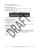
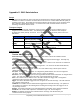
Remote Message Format
Byte Bits
Description
0xCF = Message Type 8 Bit 7:0 = 0xCF = SXL1 Remote message type:
Sensor Info 64 Sensor Defined information