
User's Manual

Wiring
Table 1 shows the maximum wire run for different wire gauges.
Table 1. Maximum wire run
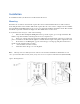
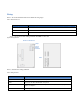
Figure 3 shows the module wiring terminals and LEDs on the board
Figure 3. Wiring terminals
Board front Board back
Tampe
r
switch
Wiring
terminals
LEDs
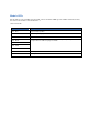
Table 2 describes the wiring terminals.
Table 2. Wiring terminals
Length in feet Wire gauge (connected to NX control panel or NX320E power supply)
10 20
50 18
100 16
Terminal Description
DATA Connect to the KP DATA terminal of the panel.
COM Connect to the KP COM terminal of the panel.
POS
Connect to the KP POS terminal of the panel. Refer to Specifications on page 24 for
power consumption.
TAMPER Normally closed.