To download a copy of this manual go to “Quick Links” at www.numerexsolutions.com.
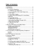
Table of Contents 1. Introduction ....................................................................... 4 2. Key Features..................................................................... 4 A. Full Event Reporting ................................................. 4 B. Telephone Line Supervision ..................................... 4 C. Panel to MODEL 2550 Cable Supervision ............... 4 D. Zone Inputs .............................................................. 4 E. Three Relay Outputs .........
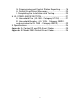
G. Programming and Central Station Reporting ......... 18 H. Default Event/Email Messages .............................. 20 I. Completing the Installation and Testing................... 20 8. UL COMPLIANCE SECTION.......................................... 21 A. Household Fire (UL 985 - Category UTOU) .......... 21 B. Household Burglary (UL 1023 - Category NBSX, and evaluated to UL 1635 - Category AMCX) ............ 22 9. Specifications ..................................................................
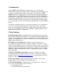
1. Introduction Uplink’s MODEL 2550 GSM Alarm Communicator is a UL Listed alarm communicator designed to interface with most manufacturer’s alarm panels that incorporate a digital telephone dialer. A key feature of the 2550 is a “dialer capture” interface to the alarm panel.
• • • • • • • • AC Loss Low or Missing Battery Telco Line Loss Panel/MODEL 2550 Cable Supervision Trouble Activation of Input(s) Unit Disabled by Dealer Command Watchdog Circuit Activation Catastrophic Failure Condition F. Power Source Monitoring (AC & Low Battery Reporting). Reports low battery conditions to the central station when voltage drops below 10.2 VDC. Reports Low Battery Restoral at 11.4 VDC. It can also be programmed to report Loss of AC power to the central station.
3. Warranty Information and Liability Waiver TERMS and CONDITIONS These terms and conditions are a legal contact between you and the Company and supplement (but do not supersede) the terms and conditions of any master agreement between you and Uplink Security, Inc. (the “Company”) governing your purchase of the Product from the Company. By using, marketing, or selling the Product, you agreement to these terms and conditions.
INDEMNIFICATION You agree to defend, hold harmless, and indemnify the Company and its affiliates and their respective officers, directors, employees, and agents from and against any and all damages, liability, costs, and expenses (including, without limitation, reasonable attorneys’ fees) arising out of or relating to (a) any claim for breach of this Agreement by you; (b) any claim for negligence, intentional misconduct, or any other act or omission on the part of you or your employees, agents, or represent
installation. This equipment generates, uses and can radiate radio frequency energy and, if not installed and used in accordance with the instructions, may cause harmful interference to radio communications. However, there is no guarantee that interference will not occur in a particular installation.
customer as soon as possible. Also, you will be advised of your right to file a complaint with the FCC if you believe it is necessary. The telephone company may make changes in its facilities, equipment, operations or procedures that could affect the operation of the equipment. If this happens, the telephone company will provide advance notice in order for you to make necessary modifications to maintain uninterrupted service.
6. Technical Support Technical support is available Monday through Friday, 8:00 AM to 8:00 PM ET excluding holidays. Before calling technical support please ensure to have read the installation guide completely. Technical support requires the caller to provide: • Login name • Password • Serial number of the 2550 UPLINK Technical Support 1600 Parkwood Circle, Suite 500 Atlanta, GA 30339 888-9-Uplink (888-987-5465) Fax: 770-693-3501 For Customer Support, call 888-987-5465, or visit www.uplink.com. 7.
SWITCH NO. S1: Default Load S2: Panel Protocol S3: Battery Mode Override S4: LED Function SETTING OFF ON OFF ON OFF ON FUNCTION Normal Operations Load defaults CID protocol SIA (Level 1 & partial Level 2) Normal Operation Battery Mode Override enabled OFF ON Normal Operations RSSI Measurements Battery Mode is a low current default that extends battery life to its maximum in accordance with UL requirements.
TROUBLE LED (#3) Green Red On On All 3 Output Relays Normal One or more Output Relay Off-Normal GSM COMM LED (#4) Green On Flashing Unit registered on the network Waiting for an ACK from the Central Station Red On Unit not registered or No Cellular Network HEARTBEAT LED (#5) Green Red Flashing Flashing Unit is functioning normally S1 is ON after reset RSSI Mode: When the 2550 is placed in Received Signal Strength Indicator (RSSI) Mode by turning Dipswitch S4 to ON, the five LEDs indicate the fol
D. Locating and Installing the 2550 The 2550 is housed in a plastic enclosure and requires an additional 16.5 VAC – 40VA transformer (Recommended Transformers: Ademco 1361, MG Electronics Model MGT1640 or equivalent) and backup 1.4 AH battery (Recommended Battery: Powersonic PS-1212 or equivalent). The recommended battery measures 3.8 inches long by 2.3 inches high by 1.7 inches wide. A battery wider than 1.7 inches will not allow for proper closure of the Uplink 2550 case.
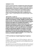
Figure 1: Parts on the 2550 PC Board 14
Position the bottom of the 2550 enclosure where it will be installed. Use four (4) #6 screws and mount the unit using the four holes in the enclosure’s plastic bottom. The 2550 unit’s dimensions are shown in Figure 2. Figure 2: Inside & Outside Mounting Dimensions for the 2550 5. Make sure the unit’s antenna is connected, then place the backup battery in its location in the bottom of the plastic enclosure. 6.
c. Disconnect the Positive and Negative connections to the battery. E. Connecting The 2550 to the Alarm Panel and Telephone Jack IMPORTANT: Make all connections to the 2550 in the powered down state. Once all connections have been established, turn power on. 1.Remove AC and battery power from the 2550, then proceed as follows: 2. Dialer & Telco Connections. a. Use the dual modular plug telephone cable provided with the 2550 to connect it to the premises’ RJ31X jack.
The default states for these 3 Outputs are as follows: Output #1 #2 #3 Default State Energized closed (N.O.) Energized closed (N.O.) Energized open (N.C.) Default Definition Loss of cellular service Failure to receive ACK from Central Station Total failure of Model 2550 See Figure 3 as an example of how to connect the 2550 to the alarm panel and the telephone line. Figure 3: Connections Between the 2550 and the Alarm Panel F.
b. Read the UPLINK Security Inc. Dealer Agreement, then click Accept Agreement. c. A box will appear saying “You hereby accept the Uplink Security Dealer Agreement?” Click OK. d. A box will appear saying “If you want monthly service billed to a 3rd party such as a central monitoring station then you should NOT request an account – please contact Uplink Sales at 888-987-5465.” Click OK. e. At this point there will be a screen entitled “Step 2. Rapid Signup – please provide Login & Contact Information”.
Programming requires the telephone number of the monitoring central station’s alarm receiver and/or its IP address and Port number. Determine whether to use the default settings for the events to be reported customize them by completing the following: Use this web site to program: a. Whether alarms will be sent to the central station via an IP connection or via a telephone dialer b. The telephone number or IP address and Port number of the central station receiver where all of the signals should be sent c.
6. Definition of Output Relays (Default = #1 Loss of Cellular Service, #2 Central Station ACK Failure, #3 Total Unit Failure) There are 11 Trouble states that be declared by the 2550, and each of these states can be programmed from the Dealer Web Site to activate one of the three Output Relays.
Test the following: a. Check to see that all 5 LEDs are green. The first 4 LEDs should be solid green, and the 5th LED should be flashing green. b. Disconnect the Telco Line, wait the appropriate period of time, then check to see that 1) the Telco LED has turned solid red, and b) a Telco Trouble condition has been reported to the monitoring central station (if this feature is active). c. With the Telco Line still disconnected, trip an alarm on the alarm panel.
6. All power-limited wiring must be secured a minimum of ¼ inch away from all non-power-limited high voltage wiring, and all non-power-limited high voltage wiring must be routed through a different conduit than any of the power-limited wiring or cable. 7. The 2550 can be used in conjunction with the alarm panel’s DACT, or it can be the only means of off-premises communication for the alarm panel. 8. The 2550 must be programmed to send a Test signal to the central station a minimum of once every 24 hours. 9.
8. The 2550 must be programmed to send a Test signal to the central station a minimum of once every 24 hours. 9. The 2550 Output Relay #1 must be programmed for Loss of Cellular Service (i.e., Network Trouble Supervision), must be connected to a reporting zone on the alarm panel, and the zone must be set up as closed in the normal state and open in the off-normal state . Activation of this zone must annunciate locally. 10.
Physical - Height - Width - Depth 2.5 inches 5.4 inches 10.
Appendix A: Contact ID and SIA Event Codes Following is a list of event codes that can be sent to the central station receiver for events generated by the AnyNET module and the 2550 unit: EVENT DESCRIPTION CONTACT ID EVENT CODE SIA DC-03 EVENT CODE E301 R301 E140 E130 R130 E137 R137 R400 E110 R110 E200 R200 E158 R158 E122 R122 E302 R302 E159 R159 E100 R100 E400 E120 R120 E350 R350 E355 R355 R140 R616 E616 E350 R350 E602 E300 R300 E330 R330 AT AR UA BA BR TA TR CL FA FR FS FJ KA KR HA HR YT YR ZA ZR MA M
Appendix B: Model 2550 Default Event Codes The 2550 is defaulted to send both the Alarm/Trouble condition the Restoral condition for all of the events listed below. Reporting individual events can be controlled from the Dealer Web Site.
UPLINK MODEL 2550 GSM ALARM COMMUNICATOR INSTALLATION, OPERATION AND PROGRAMMING GUIDE Dated 10/10/2008 © 2008 by Numerex Guide 00-25580-841-01 (rev 1.07) No part of this publication may be reproduced or used in any form without permission in writing from Numerex. This includes electronic or mechanical means, such as photocopying, recording, or information storage and retrieval systems. The material in this manual is subject to change without notice.