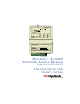
Comm Activity Network Status Service DigiCell ® AnyNET Network Access Module Network Interface Network Service ® AMPS Cellemetry GSM SMS GPRS CDMA Ethernet 1xRTT TCP/IP RS-232 Input 1 Sampled Siren S3 on, S4 on Input 1 Standard S3 off, S4 off Input 1 Pulse Ctr S3 off, S4 on Input 1 Timed Bell S3 on, S4 off S/N 9200920999 19-25133-070 IN 1 + - IN 2 + - IN 3 + - IN 4 + - OUTPUT 1 OUTPUT 2 307V100B 12 VDC + - NETWORK DIGICELL® ANYNET NETWORK ACCESS MODULE Product ID # 19-25133-070/-071 INSTA
Revision 1 Dtd 12/30/05 © 2005 by Numerex No part of this publication may be reproduced or used in any form without permission in writing from Numerex. This includes electronic or mechanical means, such as photocopying, recording, or information storage and retrieval systems. The material in this manual is subject to change without notice. Numerex reserves the right to make changes to any software or product to improve reliability, function or design.
TABLE OF CONTENTS Table of Contents ........................................................ 1 Warranty Information & Liability Waiver ..................... 1 Technical Support ........................................................ 2 Description .................................................................. 3 Installation Steps ........................................................ 4 Unit Wiring .................................................................. 6 Antenna Specification ...........
WARRANTY INFORMATION & LIABILITY WAIVER The Company's Products Are Subject To The Following Limited Warranty: The company's products are warranted against defects in materials and workmanship for a period of one (1) year following the date of purchase, under normal use and service. The company's obligation under this limited warranty is limited to repairing or replacing with reconditioned parts, at its option, any product proven to be defective in materials or workmanship under normal use and service.
TECHNICAL SUPPORT Technical support is available Monday through Friday 8:00 AM to 8:00 PM ET excluding holidays. Before calling technical support please ensure you have read the installation guide completely. Technical support requires you to provide: • Login name • Password • Serial number of the unit These items are required in order to assist you.
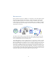
DESCRIPTION DigiCell AnyNET® Network Access Modules are comprised of various radio modules supporting multiple analog and digital radio technologies. Supported technologies include GSM, CDMA, and AMPS. Supported services include Cellemetry® and SMS for either GSM or CDMA. Support is also provided for expansion to broadband wireless. In addition, the Module can also be optionally ordered and configured with an IP communications module providing 10/100 Ethernet connectivity.
INSTALLATION STEPS 1. For new customers, establish an account with Uplink by visiting the www.uplink.com website and requesting a new account. 2. The AnyNET Module must be activated and configured from the Uplink website at www.uplink.com or by calling Uplink Support at 1-888-987-5465. 3. Install the Module’s antenna on top of the unit. 4. Before permanently installing the unit, test signal strength of the unit by connecting a 12 VDC, 2 A capable power supply. 5.
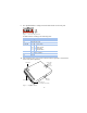
. The AnyNET Module is configured via the DIP switches on the front panel. Figure 1: Detail of Dip Switch Set DIP switches according to the following table: Switch# Settings S1 reserved (set to off) S2 reserved (set to off) S3 and S4 S3 OFF OFF ON ON S5 OFF Output 1 Normal Operation S6 reserved ON S4 OFF ON OFF ON Input 1 Type Standard Input Pulse Counter Timed Bell Sampled Siren Output 1 Trouble 10.
UNIT WIRING The location of the DIP switch, terminal block connections, network port, serial interface, and status LEDs of the Module are shown in Figure 2 on page 5. Further detailed drawings included below.
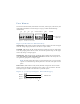
Voltage Trip - Inputs 2, 3, and 4 (and 1 if set for standard input) can be tripped by applying 12 V to the + input and 0 V to the - input. A signal must be continuously present for 500 ms. INPUT – OUTPUT From Panel INPUT + + 12 V Figure 5: Wiring example for open collector trip Open Collector - Inputs 2, 3 and 4 (and 1 if set for standard input) can be tripped by applying 12 V to the + input and the Open Collector output of the panel to the - input. A signal must be continuously present for 500 ms.
You need to assemble your serial connection cable as detailed in the graphic below. Pinouts on this connector are as follows: Pin 1 Pin 2 Pin 3 Pin 4 Data to Unit Data From Unit Ground Figure 6: Serial connector details The serial communications protocol document is available upon request. A DB9 to Molex serial cable is also available upon request from Uplink support. Optional DB25 Connector The unit may be optionally configured with a DB25 connector in place of terminal block connections.
Network Expansion Port The network expansion port is a serial RJ45 connector. This interface is essentially an interface to a modem like device. All levels are 3V TTL. 87654321 Figure 8: RJ45 Network Expansion Port NOTE: Not operational - do not use for phone Pinouts on this connector are as follows: Pin 1 2 3 4 5 6 7 8 Signal Notes Ground VCC (3.3 Volt) Reset Data Input Data Output CTS DCD RTS 3.
FCC & INDUSTRY CANADA REGULATORY COMPLIANCE This device complies with Part 15 of the FCC Rules. Operation is subject to the following two conditions: (1) this device may not cause harmful interference, and (2) this device must accept any interference received, including interference that may cause undesired operation. This equipment has been tested and found to comply with the limits for a Class B digital device, pursuant to Part 15 of the FCC Rules.
Numerex Corp www.nmrx.