
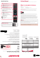
Daim Ntawv Qhia Tus Neeg Siv


Connectivity
1
2
1
2
1 2 3
1
2
3
4
5
6
7
8
9
2
1
3
K
H
J
L
I
M
G
F
E
D
C
B
A
N
Terms and conditions apply. Online registration only.
Register your manufacturers
guarantee online within
14 days of purchase at
www.registertoday.co.uk/sharp
and enter into a prize draw to
win a Sharp Soundbar
3 x
M (4x12)
1 1/2
4 x ST (4x12)
TF CARD INUART
I
K
M
J
L
N
LAN* Network Connection
Digital audio Digital optical audio output
Video Video input
L/R Audio Shared for video
HDMI 3 HDMI input
HDMI 2 HDMI input
Sat In Satellite Input
RF In RF / TV Aerial input
HDMI 1 (ARC) HDMI input with ARC
USB 2.0 USB 2.0 input x2
Earphones Earphones Input
Service Input Input used by Service Centers
TF Card In Micro SD Card input
CI card in Common interface module
HF
G
B
A C ED
3 2
1 Fitting the stand
Connect the TV to your power socket.
If you wish to use the TV to receive Freeview/Saorview channels, connect the RF input from the
TV to your outdoor Digital TV aerial. If you do not wish to receive Freeview/Saorview, skip this
step.
Wall Mounting the TV2 Connecting your set
4 First time installation
Introduction & Language
When the set fi rst turns on, it enters the First Time Installation mode. This can be restarted
by restoring the set to default settings in the ‘About TV’ Menu.
Select your preferred on-screen display language. This will change the language in which
the menus and associated information is displayed in.
Country
Select the correct country in which the set will be used in. This will enable the set to
correctly install the functions applicable in the country of use.
PIN
This needs to be set to establish parentol controls.
TV Mode
Home Mode: For normal use, by default it is set to a power saving mode which reduces
the energy used by up to 25%
(by reducing the power to the LED/LCD panel). This can be changed in the picture mode
settings.
Updates Notice
You will need to agree to certain information collection for the TV set to operate as
intended.
Network Set Up
You can connect the TV to your broadband router or wireless network in
order to take advantage of the Smart functions. If you connect the TV to
your router using an Ethernet cable, the Wifi set up will be skipped.
Channel Scan
Choose to install terrestrial channels via Digital or Analog signals.
Note: Analog signals in the United Kingdom have been turned off .
Only Digital signals are available.
Note: In home
mode, the TV
will switch off
automatically after
4 hours in the event
that no buttons are
pressed on the TV or
remote control.
Time Zone
Set the Time Zone in which the TV will reside. This may be dependent on the country you
select in step 2.
Set up Netfl ix
If you have a Netfl ix account, it can be set up on the television here. Once set up and
validated, the First Time Installation returns to the next step.
Attach the stand neck to the rear of the
TV set using the 3 x M(4x12) screws
Peel off the protective plastic cover
then attach the stand base to the neck.
Secure the base to the neck by using the
4 x ST(4X12) screws provided.
For stand installation, there are two types of screws
provided as shown below. To complete the stand
installation you will require a cross head screw driver.
Place the TV set on a fl at and clean surface with
the panel facing downwards to avoid damage.
4 x ST (4x12)
3 x M (4x12)
Used for attaching the
stand base
to the stand neck (fi g.3)
Insert the batteries supplied into
the remote control and press the
standby button to power on the TV.
Remote Control:
Installing Batteries
Stop/Eject Disc For DVD models only
Play/Pause Disc For DVD models only
Volume up and menu right
Volume down and menu left
Programme/Channel up and menu up
Programme/Channel down and menu down
Displays Menu/OSD
Displays the input source menu
Standby Power On/Off
3 Button layout
HELPFUL ADVICE FOR FIRST TIME STAND INSTALLATION
When securing the self-tapping screw/s into the base of the stand
(on fi rst installation) the screw/s will be naturally tight as they
create a thread in the plastic of the stand neck in order to support
a TV of this size.
A. Ensure the cross head screw driver tip fi ts correctly into the
head of the screw and that it is not too big or small.
B. Screw in all screws individually and partially before tightening
all of the screws fully.
C. If they become very tight try loosening them slightly and then
re-tightening them once again as this will continue the process of
creating the thread for the screws.
Setting up the TV set for the fi rst time
Remove the four screws that are supplied
in the wall mounting holes.
The wall mount can now be easily attached to
the mounting holes on the rear of the TV.
Install the wall mounting bracket to the
television as advised by the bracket
manufacturer.
The picture shows the use of spacers, which are
not applicable to all sets/installations.
Image for illustration only.
For the dimensions of the VESA mount-
ing, please refer to the Technical Specifi -
cations section of this document.
1
2
3
5
6
7
8 9
4