
Datasheet
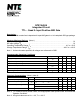

Electrical Characteristics (Cont’d): (Note 2, Note 3)
Parameter Symbol Test Conditions Min Typ Max Unit
High Level Input Current I
IH
V
CC
= MAX, V
I
= 2.7V − − 20 A
Low Level Input Current I
IL
V
CC
= MAX, V
I
= 0.4V − − −0.4 mA
Short−Circuit Output Current I
OS
V
CC
= MAX, Note 4 −20 − −100 mA
High Level Supply Current I
CCH
V
CC
= MAX, V
I
= 4.5V − 2.4 4.8 mA
Low Level Supply Current I
CCL
V
CC
= MAX, V
I
= 0V − 4.4 8.8 mA
Note 2. .For conditions shown as MIN or MAX, use the appropriate value specified under “Recommended
Operation Conditions”.
Note 3. All typical values are at V
CC
= 5V, T
A
= +25C.
Note 4. Not more than one output should be shorted at a time, and the duration of the short−circuit
should not exceed one second.
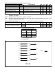
Switching Characteristics
: (V
CC
= 5V, T
A
= +25C unless otherwise specified)
Parameter Symbol Test Conditions Min Typ Max Unit
Propagation Delay Time
From A or B Input to Y Output)
t
PLH
R
L
= 2k, C
L
= 15pF − 8 15 ns
t
PHL
− 10 20 ns
Truth Table (Each Gate):
Inputs Output
A B Y
H H H
L X L
X L L
H = HIGH Voltage Level
L = LOW Voltage Level
X = Don’t Care
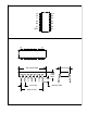
Logic Diagram
A1
B1
Y1
3
1
2
A2
B2
Y2
6
4
5
A3
B3
Y3
8
9
10
A4
B4
Y4
11
12
13
Y = A B or Y = A
+ B
Pin14 = V
CC
Pin7 = GND