
User's Manual
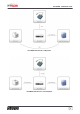

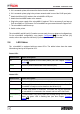


Table Of Contents

8
microMIND - Installation Guide
2.
If it is a network printer, disconnect the device from the network.
3.
If it is a network printer, plug-in the printers network cable in one of the RJ45 input jacks.
4.
Attach the MiCard (V2) reader to the microMIND's USB port.
5.
Attach the microMIND reader to the network.
6.
Plug-in the power supply of the microMIND if required. This is necessary if you have no
PoE microMIND or if you have a PoE microMIND but your network doesn't support PoE.
7.
The microMIND reader boots up.
8.
Switch on the printer.
The microMIND and MiCard (V2) reader are now ready for more advanced configurations.
For the microMIND configuration, see chapter Configuration . For the MiCard (V2)
reader, refer to the respective MiCard (V2) manual and the uniFLOW manual.
2.6
LED Status
The microMIND is equipped with two status LEDs. The tables below show the status
information given by the respective LED.
Power LED:
Status/Color
Status description
Off
No power supplied or boot loader phase (see also chapter Firmware
update ).
Green
Device is powered with Power over Ethernet (PoE).
Orange
Device is powered with an external power supply.
Status LED:
Status/Color
Status description
Off
The microMIND did not boot. It is most likely defective.
Green
A MiCard (V2) card reader is connected and has been identified. The
microMIND is ready to receive data from the MiCard (V2).
Green flashing
No USB card reader is connected. This status will only be displayed if
the microMIND is connected to the network and to a uniFLOW Server.
Green flashing
(fast)
If a new firmware has been loaded successfully during the boot loader
phase, the green LED is flashing fast (see also chapter Firmware
update ).
9
10
10