
Integration Guide


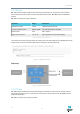

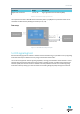


Table Of Contents

Test modes
Parameter Range Description
3GPP band number 1 to 66 nRF9160 supported bands
Frequency 100 kHz raster 6000 to 22000 Corresponds to 600 to 2200 MHz
System mode 0 to 1 NB1 = 0, M1 = 1
Signal level at antenna -50 to +23 TX signal level at antenna port [dBm]
Modulation CW to 16QAM TX signal properties - options available depending
on selected system mode
RB or SC count 1 to 12 TX signal properties - options available depending
on selected system mode
RB or SC start position 0 to 11 TX signal properties - options available depending
on selected system mode
Table 3: TX ON input parameters
The response to the test is TX signal power at antenna port measured internally by DUT. The same TX
signal power can be measured with external measurement equipment connected to DUT antenna port.
Figure 5: Example command
Test setup
Figure 6: TX test setup example
5.2.3 GPS SNR test
GPS SNR ON command executes a GPS SNR test. GPS L1 frequency is 1575.42 MHz and this test expects
the CW in signal generator to be 1575.750 MHz, i.e. 330 kHz offset from the center frequency. The
measurement duration is 1 ms.
The test is disabled automatically after 1 ms and dedicated GPS SNR OFF command is not needed.
GPS SNR ON has a one input parameter:
v1.0
14