-
Web Server – WS10 INSTRUCTIONS MANUAL V2.0x B 5000702 INDEX Index........................................................................................................................................................................................................ 1 Basic Functions ....................................................................................................................................................................................... 2 Electrical Connections .................
-
Web Server – WS10 BASIC FUNCTIONS The WS10 Web Server by Novus is an equipment capable of acquiring and delivering data using the internet technologies. Local and remote systems supervision, alarm notification and data logging are easy to configure and operate, with no dedicated software.
-
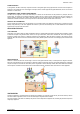
Web Server – WS10 ALARM SUPERVISION In this application, the WS10 continuously compares the content of its registers against user programmed limits. The result of this comparison is assigned to a new register that can be used to trigger a local output, write in a remote equipment through the Modbus RTU, send an e-mail or send information to a remote server. TRANSMISSION OF E-MAIL OR MOBILE PHONE MESSAGES The WS10 can be configured to send e-mails automatically to an address list.
-
Web Server – WS10 ELECTRICAL CONNECTIONS POWER SUPPLY Terminals 17 and 18 are the power supply inputs of the WS10, accepting any voltage input between 100 and 240 Vac. A few seconds after poweron the STATUS indicator blinks, indicating the WS10 is running. The mains power should be one proper for instrumentation or computers.
-
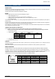
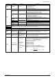
Web Server – WS10 USING THE RS232 WITH RS232/RS485 CONVERTERS The WS10 is ready to accept an external RS232 / 485 converter on its SERIAL 2 (RS232) communication port. Converters like the Novus ISO485-1 and ISO485-2, in the RTS mode, can be used. The DTR signal is kept fixed in +5V and used to power the RS232 side of the converter. The CTS signal is also kept fixed in +5 V to enable the WS10 for transmitting. The RJ12 to DB9 or DB25 cable adaptor is described in the table below.
-
Web Server – WS10 WS10 CONFIGURATION Installing and configuring the WS10 require networking expertise. Consult your company’s network administrator. GENERAL INFORMATION The WS10 configuration is accomplished through the Ethernet interface making use of ordinary network programs: FTP (File Transfer Protocol – for transferring files to/from the WS10) and Telnet (to access the configuration console).
-
Web Server – WS10 If the error persists, not allowing the FTP connection, perform a WS10 reboot and try again using the username and password in the address line as suggested above. To solve further FTP connection errors, we recommend the usage of dedicated FTP client software. There are many shareware and freeware options available for download on the Internet. In the WS10 CD are included some of these FTP softwares.
-
Web Server – WS10 The WS10 configuration files are: MODBUS.CFG LOCALIO.CFG WEBS.CFG PPP.CFG MODBUS2.CFG CLITCP.CFG DATALOG.CFG ALARMS.CFG MAIL.CFG MODBTCP.CFG MAP.CFG DNS.
-
Web Server – WS10 LOCAL INPUTS AND OUTPUTS CONFIGURATIONS The built-in inputs and outputs are configured on the LOCALIO.CFG file. Only the selection between voltage and current input is accomplished in hardware. All other configurations are done on this file, exemplified below. [General] AChannels=1 DecimalSeparator=. [Input1] Tag=LIN1 Logic=1 PullUp=2 Debounce=1 CalLow=0 CalHigh=1023 [Input2] Tag=LIN2 Logic=1 PullUp=1 Debounce=0 CalLow=0 CalHigh=1023 TotTag=TOT2 Interval=10 [Input3] ... [Input4] ..
-
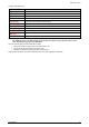
Web Server – WS10 Section General Parameter Values AChannels 0, 1, 2 or 4 Tag Up to 6 characters or digits Logic 0 or 1 PullUp 0, 1 or 2 Debounce 0 or 1 CalLow CalHigh Flow Sub-section TotTag Flow Sub-section Interval See section Local Inputs Calibration Input1 Input2 Input3 Input4 Output1 Output2 Memory Memory-Hold Aliases Up to 6 characters or digits 1 to 30000 The same parameters described for Input1 are repeated under the sections for the 3 other inputs.
-
Web Server – WS10 LOCAL INPUTS CALIBRATION Before using a local input as analog input, it must be calibrated. The local inputs have a 10 bits resolution and a measurement range from 0 to 5V or 0 to 20mA. The calibration procedure allows configuration of the measured value range, to achieve the desired result in engineering units. Calibration is configured in 2 parameters for each channel on the LOCALIO.CFG file: CalLow and CalHigh.
-
Web Server – WS10 MODBUS RTU NETWORK CONFIGURATION – WS10 AS MASTER The WS10 can be configured as a Modbus master, and can read or write on memory locations of other Modbus devices on the same network. If the MODBUS.CFG file exists on the WS10, this function is enabled and the WS10 starts scanning the network according to the configuration of devices and registers. Values read from the external devices are stored on the WS10 memory and are identified by a device/tag name.
-
Web Server – WS10 REFERENCE TO THE MODBUS ACQUIRED TAGS Reference to the WS10 registers associated to external Modbus RTU devices are done through the device and tag name defined at the MODBUS.CFG file, using one of the syntax options bellow. Only registers read with commands 3 (default command) and 1 accepts write operation.
-
Web Server – WS10 ALARMS SUPERVISION CONFIGURATION The WS10 can compare the value of any register against limits defined as constants or other registers. The result of the comparison is assigned to a new alarm register. Based on the result of the alarm, registers can be written to, allowing the WS10 to take actions based on the detected alarm condition.
-
Web Server – WS10 DATA LOGGER CONFIGURATION The WS10 can be programmed to periodically save a set of register values and time stamps on its flash memory as a file. This file can be transferred to the PC using FTP or can be automatically sent as an email attachment. Attention: The data logger is stopped during the transmission of the data. The data logger function is enabled when the DATALOG.CFG is installed on the WS10. Follows an example of the DATALOG.CFG file: [General] ID=LOGGER1 File=A:\LOG\DATALOG.
-
Web Server – WS10 DATA LOGGER FILE FORMAT A new line is appended to the log file at each interval. The first line contains the identifiers, and all following lines contain the values of the listed registers. The first 2 columns of a log line contain the date and time, and the following columns contain the values for each register. Columns are separated by the comma character. File layout: Log ID Empty field Identifier 1 Identifier 2 ...
-
Web Server – WS10 HTML PAGE SERVER CONFIGURATION The WS10 can store and serve HTML files. All files accessed through http must be stored in the WEB folder or in its sub-folders. Use FTP to include and exclude files. It is not necessary to reboot the WS10 when new or updated files are transferred to the WS10. The new page version will be displayed on the next browser refresh. The default page of the WS10 is named MAIN.HTM.
-
Web Server – WS10 The MAIN.HTM page can not display register values. To display dynamic data in the start page, define frames inside MAIN.HTM and include register references in separate HTML files. The MAIN.HTM page can also switch automatically to the page which actually displays the register values. See example of redirection to DATA.HTM below:
PAGE 19
Web Server – WS10 USAGE OF CGI TO SEND VALUES TO THE WS10 An HTML formulary can write to a WS10 register using the POST method. The WS10 built in CGI script associate the formulary values to the WS10 registers. The example 3 show the use of the POST method to write on the WS10 real time clock registers and on 3 other registers. The CGI script name defined at the [Auth] section of the WEBS.CFG file must match to the name used at the page Forms.
-
Web Server – WS10 PERIODICAL DATA TRANSMISSION CONFIGURATION The WS10 can be configured to periodically send data to a host computer. This host computer must run a dedicated application that accepts a socket connection requested by the WS10 and receive and store the sent data on files or database. The periodical data transmission function of the WS10 is enabled by the inclusion of the CLITCP.CFG file at the WS10. There are 2 output paths for the TCP data: Ethernet or PPP (modem).
-
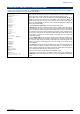
Web Server – WS10 Section Parameters Values Address Host IP address Port SendRate 0 to 65535 0 to 65535 KeepAlive 0 or 1 LinkType ETH or PPP ID WS10 identification with up to 10 characters Device/Tag of the registers to be sent Alternative name for the register, with up to 24 characters. General VarList TriggerList Device/Tag list Description IP address of the host computer. Must be accessible through the specified connection.
-
Web Server – WS10 E-MAIL CONFIGURATION The WS10 can send multiple e-mail messages, containing dynamic information. Messages can be sent periodically or by exception, based on register values. Both the subject and body of the message can contain dynamic data. The data logger file can be included on any message as an attachment. Some typical applications of the e-mail function: • Periodically send system data, including data logger file.
-
Web Server – WS10 Section Sub-Section Parameter Values Description Type of connection. ETH or PPP ETH: Ethernet. LinkType PPP: PPP connection configured at the PPP.CFG file. IP address of the SMTP server. Must be accessible through the IP address specified connection. If a DNS configuration exists, a domain name can SMTPServer be specified in substitution of the IP address. Port used to connect the SMTP Server. If this parameter is not set the SMTP Port SMTPPort Port 25 will be assumend as standard.
-
Web Server – WS10 MODBUS RTU NETWORK CONFIGURATION – WS10 AS SLAVE The WS10 can be configured to act as a Modbus RTU slave on a serial port. When the WS10 is a Modbus RTU master on one serial port and slave on the other serial port, it can be used as a Modbus RTU concentrator. Assignment of unique addresses to the WS10 registers are defined by the user in the MAP.CFG file, as described in section “Registers Address Map for Modbus TCP and Modbus RTU-Slave”.
-
Web Server – WS10 MODBUS TCP NETWORK CONFIGURATION – WS10 AS SERVER OR GATEWAY Configuration of this function requires knowledge on ModbusRTU and ModbusTCP protocols. Full protocol documentation can be obtained at www.modbus.org. Before including WS10 in a SCADA system, check if SCADA supports ModbusTCP. OVERVIEW WS10 can be configured to operate on a ModbusTCP network as a Server or gateway. A Server accepts connection requests issued by a client, and answers to its messages.
-
Web Server – WS10 PARAMETERS ModbusTCP function is enabled when file MODBTCP.CFG is included in the WS10. Follows an example of this file: [General] ServerPort = 502 ServerID = 255 IdleTimeOut = 300 MaxConnections = 4 MultipleConnections = true [Rules] Allow 10.1.1.0 mask 255.255.255.0 Allow 200.200.200.200 Deny 192.168.0.0 mask 255.255.255.
-
Web Server – WS10 CONFIGURING THE MODEM TO START A DATA CALL – PPP CLIENT When a modem is connected to one of the serial ports (usually the serial port 2), the WS10 can be configured to start a data call using PPP (Point to Point Protocol). The WS10 will act as a PPP client and at the other side a PPP server will respond to the connection request. The PPP.CFG file contains the configuration of the PPP client function.
-
Web Server – WS10 Section General Connection Parameter COM 1 or 2 Values Auth 0 to 4 Flow 0, 1 or 2 Baud 300, 600, 1200, 2400, 4800, 9600, 19200, 38400 IdleTimeout 0 to 65535 RetryDelay 0 to 65535 String0 Answer0 Modem command Modem Answer Timeout0 0 to 65535 Retries0 0 to 65535 ...
-
Web Server – WS10 CONFIGURING THE MODEM TO RECEIVE A DATA CALL – PPP SERVER The PPP server is implemented on the WS10 operating system, and is configured on the system file CHIP.INI. The WS10 can act as a PPP server and answer a phone call, negotiate modem and PPP connection and assign IP parameters to the calling computer. The WS10 may also be configured to answer data calls, as described in Configuring the modem to start a data call.
-
Web Server – WS10 DNS CONFIGURATION When configuring IP addresses for e-mail and periodical data transmission functions, domain names can be defined for the servers. To resolve the domain names, WS10 needs access to a DNS Server. If WS10 is using dynamic IP (DHCP enabled), possibly a DNS address has been assigned by the DHCP server. If WS10 is using a fixed IP or if the assigned DNS address is invalid, a DNS configuration can be established for the WS10 by including a file DNS.
-
Web Server – WS10 SECUTITY ISSUES ON THE WS10 TELNET ACCESS Up to 2 authorized telnet users can be configured on the WS10. With factory settings, the WS10 has one configured telnet user (telnet/telnet). Since the second user is not configured, a default user is also enabled, with user name and password tel. The telnet console can be disabled, but it is not recommended since it is the main configuration tool for the WS10. To increase the security level, configure both telnet users.
-
Web Server – WS10 SPECIFICATIONS GENERAL Switching power supply, 100 to 240 Vac / 4VA. Operating environment: 0 to 55 °C, 35 % to 85 % RH, no condensation. ABS housing for DIN rail mount. Dimensions: 105 x 90 x 60 mm COMMUNICATION INTERFACES Two serial interfaces with 6 pin RJ12 connection. Options: • RS232. • RS485 with optical isolation. Modbus RTU master or slave protocol. • Internal V34+ Modem Ethernet 10/100. RJ45 connection.
-
Web Server – WS10 APPENDIX A Screenshots of the HTML examples.