
User Manual


Controller N3000
NOVUS AUTOMATION 7/9
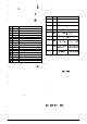
RAMP AND SOAK PROFILE PROGRAM
Seven ramp and soak profiles with up to 7 segments each can be
programmed. Longer profiles of up to 49 segments can be c reated by
linking 2 or more profiles.
SP
time
T1
T2
T3
T4
T5
SP0
SP1
SP2
SP3
SP4
SP5
SP6
SP7
T6
T7
SV
time
T1
T2
T3
SP0
SP1
SP2
SP3
T4=0
Figure 11 - Exampl e of a complete r am p
and soak profile
Figure 12 - Exampl e of a profi le
with fewer segment s. (T4 is set 0)
To execute a profile with fewer segments just program 0 (zero) for the
time intervals that follow the last segment to be executed.
The program tolerance “
Ptol
” defines the maximum deviation
between PV and SV for the executi on of the profi l e. If thi s devi ati on is
exceeded, the program will be interrupted until the deviation falls to
within the tolerance band.
Programming 0 (zero) at this prompt disables the tolerance and the
profile execution will not to be halted even if PV does not follow SV
(time priority as opposed to SV priority).
The ramp and soak event function is used to activate alarms at any
segment of program 1. This applies only to program 1.
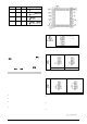
LINK OF PROGRAMS
It is possible to create a more complex program, with up to 49
segments, joining the seven programs. This way, at the end of a
program execution the controller immediately starts to run another one.
When a program is created, it must be defined in the “
LP
" screen
whether there will be or not another program.
To make the controller run a given program or many programs
continuousl y, it i s only nec essary to l ink a program to its elf or the last
program to the first.
SV
time
T1
T2
T3
T4
T5
T1
T2
T3
T4
SP0
SP1
SP2
SP3
SP4
SP5 / SP0
SP1
SP2
SP3
SP4
Program 1
Program 2
Figure 13 - Exampl e of two l inked programs
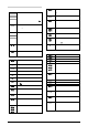
EVENT ALARM
To enable this event function the alarms to be activated must be
selected for
rS
func tion and are programmed at the
PE 0
to
PE 5
prompts. The number to be programmed at the prompt defines the
alarms to be activated (Table 5).
CODE
ALARM 1
ALARM 2
ALARM 3
ALARM 4
0
1
X
2
X
3
X X
4
X
5
X
X
6
X
X
7
X
X
X
8
X
9
X
X
10
X
X
11
X
X
X
12
X
X
13
X X X
14
X
X
X
15
X
X
X
X
Table 5 - Event c odes for ramp and soak
To configure and execute a ramp and soak program:
• Program the tolerance value, SV, time and event.
• If any event alarm is required program the ramp and soak event
function.
• Set the control mode to automatic.
• Select ramp and soak program to be executed at prompt
Prn
(0 to 7)
• Start control at the
rvn
prompt by selecting YES.
Before executing the program the c ontroller waits for PV to reach the
first set point SP0 if
PtoL
is different than zero.
Should any power failure occur the controller resumes at the
beginning of the segment it currently is.
AUTO TUNE
During auto tune the process is controlled in ON/OFF mode at the
programmed SetPoint (SV). Depending on the process
characteristi cs large osci llations abov e and below SV may occur and
auto tuning may take several minutes to be concluded.
The recommended procedure is as follows:
• Disable the control output at the
rvn
prompt by selecting NO.
• Select auto mode operation at the
Avto
prompt by selecting YES.
• Disabl e the ramp and soak function (select NO) and program a new
SV value other than the present PV (close to the desired set point).
• Enable auto tuning at the
Atvn
prompt by selecting YES.
• Enable the control output at the
rvn
prompt by selecting YES.
During the auto tune procedure the soft-start function wi ll not operate
and large oscill ations wil l be i nduced around the setpoint. Make s ure
the process can accept these oscillations and fast control output
changes.
If auto tuning results are not satisfactory refer to Table 6 for manual
fine tuning procedure.
PARAMETER RESPONSE SOLUTION
Proport ional Band Slow Response Decrease
Large Oscillation
Increase
Integr al Rate
Slow Response
Incre ase
Large Oscillation
Decrease
Derivative Time
Slow Response or I nstabi lity
Decrease
Large Oscillation Increase
Table 6 - Suggestions for m anual tuning of PID param eters
CALIBRATION
INPUT CALIBRATION
All i nputs are fac tory c ali brated and recal i bration s hould onl y be done
by qualified personnel. If you are not familiar with these procedures
do not attempt to calibrate this instrument. The calibration steps are:
a) Select the input type to be calibrated.
b) Set the desired upper and lower display limits.
c) At the input terminals i nject an electrical signal corresponding to
a known indication value a little higher than the lower display
limit.
d) Select the
inL(
prompt. Through the and keys adj ust
PV so that it matches the injected signal.
e) Inject a signal that corresponds to a value a little lower than the
upper limit of the display.
f) Select the
ink(
prompt. Through the and keys adj ust
PV so that it matches the injected signal.
g) Repeat steps c) to f) to improve calibration.
Note: When verifications are proceded, note if the Pt100
excitati on/activation current the calibrator requi res is compli ant to the
Pt100 excitation current used in this instrument: 0.750 mA.