
User Manual


Controller N3000
NOVUS AUTOMATION 6/9
CONFIGURATION CYCLE
type
INPUT TYPE: Selects the input signal type to be
connected to the process variable input. Refer to
Table 1.
This is t h e first parameter to b e set.
dppo
DECIMAL POINT POSITION: For input types 16, 17,
18 or 19 only. Selects the decimal point position to be
viewed in both PV and SV.
vnIt
TEMPERATURE INDICATION IN ºC OR ºF: Selects
the display indication to be in ºC or ºF. Only available
if input ty pe is ot her than 16, 17, 18 or 19.
offs
SENSOR OFFSET: Offset value to be added to the
PV to com pensate s ensor er ror. D efault value: zero.
spll
SET POINT LOW LIMIT:
-
Linear inputs: Sets the lower range for SV and PV
indication.
- T/C and Pt 100 inputs : set s the low er range for SV.
spxl
SET POINT HIGH LIMIT:
- Linear inputs: Sets the upper range for SV an
d PV
indication.
- T/C and Pt 100 inputs : set s the upper range for SV .
rsll
REMOTE SET POINT LOW LIMIT: Selects the lower
range for indication of the Remote Setpoint.
rsxl
REMOTE SET POINT HIGH LIMIT: Selects the upper
range for indication of the Remote S etpoint.
bavd
DIGITAL COMMUNICATON BAUD RATE
SELECTION:
0: 1200bps; 1: 2400bps; 2: 4800bps ; 3: 9600bps; 4:
19200bps.
addr
SLAVE ADDRESS SELECTION: Identifies a slave in
the networ k. The possible addres s numbers are from 1
to 247.
I/O CYCLE (INPUTS AND OUTPUTS)
Io 1
I/O 1 FUNCTION: Selects the I/O function to be used
at I/O 1 (relay 1). Options 0 to 5 are possible for this
output. It is normally used as option 5, PWM main
control output. Refer to Table 2 for functions.
Io 2
I/O 2 FUNCTION: Selects the I/O function to be used
at I/O 2 (relay 2). Options 0 to 5 are available. This
output is normally used as alarm output. See Table 2
for f uncti ons.
Io 3
I/O 3 FUNCTION: Selects the I/O function to be used
at I/O 3 (option 1). I/O 3 can be a relay output or a
digital input/output. Functions 0 to 10 are available.
Refer to Table 2 for functions. The presence of this I/O
option is detected by the controller and the prompt
menu will only be shown if the expansion option is
available.
Io 4
I/O 4 FUNCTION: Selects the I/O function to be used
at I/O 4 (option 2). I/O 4 can be a digital input/output.
Functions 0 to 10 are available. Refer to Table 2 for
functions. The prompt menu will only be shown if the
expansion option is present.
Io 5
I/O 5 FUNCTION: Selects the I/O function to be used
at I/O 5 (Analog Output). Functions 0 to 15 are
available (See Table 2). This option is normally used
for mai n contr ol output or PV analog r etrans m iss ion.
I o 6
I/O 6 FUNCTION: Selects the I/O function to be used
at I/O 6 (D igital Input). Options 0, 6, 7, 8, 9 and 10 are
possible for this input. Refer to Table 2 for func tions .
f.fvnc
F KEY FUNCTION: Selects the I/O function assigned
to the f ront panel
key . Avai lable functions are:
0
- Key not used;
7
- Start/Stop the controller (RUN function);
8
- Select rem ote set point;
9
- Execute/ Hold ramp and soak profile;
10
- Enable/Di sable r am p and soak pr ofile 1;
Detail s on these functions are described i n section 5.2.
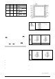
Figure 7 s hows the sequence of c ycles and parameters presented in
the indicator display. There are parameters that must be defined for
each alarm available.
Operation
Cycle
Auto
Tuning
Cycle
Programming
Cycle
Alarm
Cycle
Configuration
Cycle
I/Os
Cycle
PV e SP
atvn
Tbas
fva1 -
fva4
type
io1
avto
pb
pr n
bla1 -
bla4
dppo
io2
PV e MV
hyst
Ptol
kya1 -
kya4
vnit
io3
pr n
ir
psp0 -
psp7
A1t1
offs
Io4
rvn
dt
pt1 -
pt7
a1t2
spll
Io5
(t
pe1 -
pe7
a2t1
spkl
Io6
a(t
Lp
a2t2
rsll
f.fvnc
bias
Rskl
Figure 10 - Sequence of cyc les and parameter s pres ented in t he contr oller display
CALIBRATION CYCLE
All input and output types are factory calibrated. This cycle should
only be acces sed by experienced personnel. If in doubt do not press
the
or keys in this cycle.
Inl(
INPUT LOW CALIBRATION: Sets the Process
Variable low calibration (offset). Severa l keystrokes at
or
might be necessary to increment one
digit.
Inx(
INPUT HIGH CALIBRATION: Sets the Process
Variabl e span cal ibration (gain).
ovll
OUTPUT LOW CALIBRATION: Sets the analog
current output low calibration (offset).
Ovx(
OUTPUT HIGH CALIBRATION: Sets the analog
current output span c alibration (gai n).
(j l
COLD JUNCTION OFFSET CALIBRATION: Sets the
cold j uncti on offs et calibration.
xtyp
HARDWARE TYPE: Configures the controller to
recognize the actual installed opti
onal hardware
(accessories). The parameters menu will show the
parameters relative to the optional hardware:
0
- no opti onals or c/ RS485 onl y;
1
- relay 3 (I/O 3);
2
- Digi tal I/O (2 i nputs/outputs : I/O 3 and I/O4) ;
3
- Heater break protec tion (option) ;
Rsl(
REMOTE SET POINT LOW CALIBRATION: Sets the
Remote Set Point low calibration (offset). Several
keystrokes at or
might be necessary to
incr em ent one digit.
Rsx(
REMOTE SET POINT HIGH CALIBRATION: Sets the
Remote Set Point s pan calibration (gain).