
User Manual


Controller N3000
NOVUS AUTOMATION 3/9
Alarm F unction
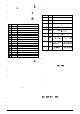
T1 T2 ACTION
Normal 0 0
Alarm Event
Alarm
Output
Delayed 0 1s to 6500s
Alarm Event
Alarm
Output
T2
Pulse 1s to
6500s
0
Alarm Event
Alarm
Output
T1
Oscillator 1s to
6500s
1s to 6500s
Alarm Event
Alarm
Output
T1
T2
T1
Table 4 - Advanced Ti m er Alarm (for alarms 1 or 2)
ALARM INITIAL BLOCKING
The initial blocking option inhibits the alarm from being recognized if
an alarm condition is present when the controller is first energized.
The alarm will actuate only after the occurrence of a non alarm
condition followed by a new occurrence for the alarm.
The initial blocking is disabled for the sensor break alarm function.
SQUARE ROOT EXTRACTION
Available when input type 19 is selected. The indicator displays the
square root of the current signal input applied to terminals 22 and 24.
ANALOG RETRANSMISSION OF PV AND SP
The analog output, when not used for control purposes, is available
for retransmitting the SV and SP values in 0-20 or 4-20 mA. This
analog output is electrically isolated from other inputs and outputs.
The analog output signal is scaleable, with the output range
determined by the val ues programmed in the parameters “
SPLL
” and
“
SPkL
”. To obtain a voltage output, connect a resistor shunt to the
current output terminals (terminal 1 and 2).
SOFT START
Defines the time interval for the output to reach its maximum value
(100 %). The soft start value is programmed in “
SfSt
”. See also
parameters “
ovLL
” and “
ovkL
”.
INSTALLATION / CONNECTION
Insert the unit into the panel cut-out and slide the mounting clamp
from the rear to a firm grip at the panel.
All elec trical connect ions are made to the screw terminals at the rear
of the controller. They accept wire sizes from 0.5 to 1.5 mm2 (16 to
22 AWG). The terminals should be tightened to a torque of 0.4 Nm
(3.5 lb in).
To minimize the pick-up of electrical noise, the low voltage DC
connections and the sensor input wiring shoul d be routed away from
high-current power conductors. If this is impractical, use shielded
cables. In general, keep cable lengths to a minimum.
RECOMMENDATIONS FOR INSTALLATION
• Input signal wires should be laid out away from power lines and
preferably inside grounded conduits.
• Instrument mains (line) supply should be suitable for this purpose
and should not be shared.
• In controlling and monitoring applications, possible consequences
of any system fail ure must be considered in adv ance. The internal
alarm relay does not warrant total protection.
• Use of RC filters (47 R and 100 nF, serial) are highly
recommended when driving solenoids, contactor coils or other
inductive loads.
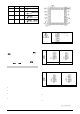
Figure 1 – Back panel termi nals
POWER WIRING
If hi gh voltage is
applied to a low
volt age input,
irr evers ible damage
will occur
Figure 2 – High and Low Volt age AC power wiring
INPUT CONNECTIONS
• Thermocouple and Voltage (Volts and mV) input connect as in
Figure 3.
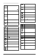
Figure 3 – T/C and Volt age
wiring
Figura 4 – Pt100 wiring with
three conductors
• RTD (Pt100)
Figure 4 shows the Pt100 wiring, for 3 conductors. Terminals 10, 11 and 12
must have the same wire resistance for proper cable length compensation.
For 2 wir e P t100, s hort c ircuit terminals 10 and 11.
Figura 5 – connect ion of 4-20 mA
Figura 6 – Connecti on of 5 Vdc
• 4-20 mA:
Refer to Figure 5. (The controller provides an internal electronic
shunt for the input current. No changes in the circuit are necessary).
• Alarm and output connection
When I/O channels are set up as output channels, they must have
their capacity respected, according do specifications.
• Remote setpoint:
The remote Setpoint (SP) is enabled by an external digital signal in
either I/O 5 or I/O6, when programmed with t he code 8 (Sel ect remote
SP input).An external resistor shunt of 100 is required between the
terminals 7 and 8.
DIGITAL INPUT