
User Manual


Controller N3000
NOVUS AUTOMATION 2/9
• CODE 7 - Digital input - Standard for I/O5, I/O6 and key.
Start/Stop input (“
rvn
”: YES / no).
Closed: outputs enabled
Opened: outputs disabled
• CODE 8 - Digital input - Standard for I/O5, I/O6 and
key.
Closed: remote SP (4-20 mA in remote SP input)
Opened: main SP (internal programmed SV)
• CODE 9 - Digital input - Standard for I/O5, I/O6 and key.
Opened: enables R&S program
Closed: holds R&S program (the program resumes when the
contact is opened again)
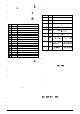
CODE
I/O TYPE I/O FUNCTION
0
Digit al Output Digit al Output to be set by the serial comm.
1
Digit al Output Alarm 1 Output
2
Digit al Output Alarm 2 Output
3
Digit al Output Alarm 3 Output
4
Digit al Output Alarm 4 Output
5
Digit al Output PWM Contr ol Output
6
Digit al Input Automatic/M anual mode change
7
Digit al Input Run/Stop mode change
8
Digit al Input Select Remote Set P oint Input
9
Digit al Input Executes/ H olds s elected ramp and soak profile
10
Digit al Input Enable/Di sable R&S profile 1 selection
11
Analog Output 0 to 20mA Analog contr ol output
12
Analog Output 4 to 20mA Analog control output
13
Analog Output 0 to 20mA PV r etrans mission
14
Analog Output 4 to 20mA PV r etrans mission
15
Analog Output 0 to 20mA SP r etrans mission
16
Analog Output 4 to 20mA SP r etrans mission
Table 2 - I/O c hannel functions
• CODE 10 - Digital input - Standard for I/O5, I/O6 and key.
Selects R&S program 1. Used to alternate between the main
Setpoint and a second Setpoint defined by the R&S program 1.
Closed: selects program 1
Opened: uses main Setpoint
• CODE 11 - Analog control output - I/O5 only. 0-20 mA control
output.
• CODE 12 - Analog control output - I/O5 only. 4-20 mA control
output.
• CODES 13 to 16 - Analog retransmission. I/O5 only. Configures
I/O5 to output a 0-20 mA or 4-20 mA analog si gnal proportional to
PV or SP.
REMOTE SETPOINT
The remote Setpoint (SP) is enabled by an external digital signal in
either I/O 5 or I/O6, when programmed with t he code 8 (Sel ect remote
SP input).
An external resi stor s hunt of 100 Ω i s requi red between the terminal s
7 and 8.
ALARMS FUNCTION
The controller has 4 alarms. The alarms can the configured to
operate in any of the nine functions listed on Table 3.
• Open sensor
It is activated whenever the input sensor is broken or disconnected.
• Event alarm
It activates alarm(s) in specific segments of the program. See item
7.2 in this manual.
• Event alarm
Detects a heater broken condition, by monitoring the load current
when the control output is activated. This alarm function requires an
optional device (option 3). Details of the "resistance fail" option can
be found in a specific documentation that is sent with the product
when the option is purchased.
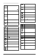
TYPE PROMPT
ACTION
Disabled
off
No active alarm. Thi s output can be used as a digital
output t o be set by the serial communication.
Sensor Break
(input E rror)
ierr
Alarm will be ON if PV s ensor br eaks, input s ignal is
out of r ange or Pt100 is shorted.
Event Alarm
(ramp and
Soak)
rs
Can be activated at a specifi c segment of ram p and
soak program.
Detection
resi stance fail
rfail
Detects a heater brok en condition
Low Alarm
lo
SPAn
PV
High Alar m
ki
SPAn
PV
LOW
Differential
difl
SV
PV
SV - SPAn
posit ive SPAn
SV
PV
SV - SPAn
negativ e S PA n
HIGH
Differential
difk
SV
PV
SV + SPAn
positi ve SPAn
SV
PV
SV + SPAn
negativ e S PA n
Differential
dif
SV
PV
SV + SPAn
SV - SPAn
positi ve SPAn
SV
PV
SV - SPAn
SV + SPAn
negativ e S PA n
Table 3 - Alarm functi ons
Where SPAn means “SPA1”, “SPA2”, “SPA2” and “SPA4”.
• Minimum value
It is activ ated when the measured value i s below the val ue defined in
the alarm Setpoint.
• Maximum value
It is act iv ated when the meas ured v al ue is above the v al ue defined i n
the alarm Setpoint.
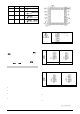
• Differential (or Band)
In this function, the parameters “
SPA1
”, “
SPA2
” represent the PV
deviation as compared to the main SP.
In a positive deviation, the differential alarm will be triggered when
the measured value is out of the range defined in:
( SP – Deviation) and (SP + Deviation)
In a negative deviation, the differential alarm will be triggered when
the measured value is within the range defined above.
• Minimum differential
It is activated when the measured value is below the value defined in.
(SP - Deviation)
• Maximum differential
It is activated when the measured value is above the value defined in:
(SP + Deviation)
ALARM TIMER FUNCTIONS
Alarms 1 and 2 can be programmed to have timer functions. The 3
modes of operation are:
1- Pulse 2- delayed actuation 3- Oscillator
The desired function can be achieved programming the parameters
“
A1t1
”, “
A1t2
”, “
A2t1
” and “
A2t2
” (see Table 4).
The LEDs associated to the alarms will light when the alarm condition
is recogniz ed, not following the actual s tate of the output, which may
be temporarily OFF because of the temporization.