Adam Equipment PW SERIES (P.N. 8081, Revision E4, September 2007) Software rev.: 2.
Page 2 of 48 © Adam Equipment Company 2007
Page 3 of 48 TABLE OF CONTENTS 1.0 KNOW YOUR BALANCE .......................................................................................... 5 2.0 SPECIFICATIONS .................................................................................................... 6 3.0 UNPACKING THE BALANCE ................................................................................... 7 4.0 LOCATING THE BALANCE ...................................................................................... 7 5.
Page 4 of 48 13.2 ENABLE WEIGHING MODES ............................................................................ 31 13.3 ENABLE SERIAL INTERFACE PARAMETERS ................................................. 31 13.4 SETUP PARAMETERS ...................................................................................... 33 13.5 CALIBRATION SETUP ....................................................................................... 34 13.5.1 INTERNAL CALIBRATION MASS ADJUSTMENT .............................
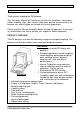
Page 5 of 48 1.0 KNOW YOUR BALANCE Thank you for selecting the PW Balance. This Instruction Manual will familiarise you with the installation, accessories, trouble-shooting, after sales service information, general maintenance of the balance, etc. and will guide you through the various applications. Please read this Manual thoroughly before starting the operation. If you need any clarifications, feel free to contact your supplier or Adam Equipment.
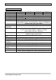
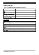
Page 6 of 48 2.0 SPECIFICATIONS Model Maximum Capacity Readability Tare Range Repeatability (S.D.) Linearity (±) Units of measure Interface Operating temperature Power supply Calibration External Calibration mass Display Draught shield Draught shield dimensions Housing Pan size Overall dimensions (wxdxh) Net weight Applications PW 124 120g PW 184 180g PW 214 210g PW 254 250g 0.0001g Full 0.00015g 0.0002g 0.
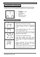
Page 7 of 48 3.0 UNPACKING THE BALANCE Remove the balance from the packing by carefully lifting it out of the box. Inside the box you will find everything needed to start using the balance AC adapter Rectangular base plate Locating disc Weighing platform Guard ring Stainless steel top pan This User Manual 4.0 LOCATING THE BALANCE • The balance should not be placed in a location that will reduce the accuracy. • Avoid extremes of temperature.
Page 8 of 48 5.0 SETTING UP THE BALANCE 5.1 ASSEMBLING THE BALANCE • Locate balance on solid surface, free from vibration • Open the sliding door and gently place the square base plate, the locating disc, weighing platform, the guard ring and then the stainless steel top. • Level balance using the adjustable feet and spirit level • Connect the power to the balance • For best performance, let the balance warm up for 30-60 min. and calibrate before using 5.
Page 9 of 48 Before you start weighing, you have to wait for the balance to achieve a stable internal temperature. Typical initial warm-up time suggested for a balance already at room temperature is about 1 hour. A stable sign ~ is shown when the balance is stable. It will turn off if the balance is not stable. Exact zero is shown when the “ 0 “ symbol is on to the left of the display area. 6.
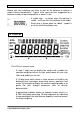
Page 10 of 48 SYMBOLS AND TEXT The LCD has unique symbols to indicate the following: 0 Zero Busy Stable A bar graph with set point markers g, mg, ct, oz, lb, ozt, GN, dwt, Text is shown for the weighing units and modes dr, tl H, tl T, tl S, MM, T, ti, N, g/cc, Pcs, %, M, and S INDICATORS “CAL” “ºC” “ti” “Net” “PARTS” “PERCENT” “NT” “0%”, “100%” When calibration is occurring or about to occur When a temperature is shown or a temperature driven calibration is to occur For a time driven calibration When
Page 11 of 48 7.0 KEYPAD The keypad has the following keys to operate the balance. Keys [ 0/T] or [Esc] [Unit] / or [Down] [Mode] / or [Advance] Primary function To turn the balance to ON or Standby A combined zero and tare function Selects weighing units by cycling through a set of enabled units Enters the Modes [Print] / or [Back] [Cal] / or [Up] Instructs the balance to print data Starts the calibration function [Setup]/ or [Enter] Enters the Setup parameters (Supervisor Menus) 7.
Page 12 of 48 8.0 INPUT/OUTPUT The rear panel has connectors for RS-232 serial and a power input socket. Required power input is a low-voltage external supply, 15VDC @ 800mA.
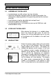
Page 13 of 48 9.0 OPERATIONS 9.1 INITIALISATION When the balance is first switched on, it will display the balance serial number (if set), software revision, model capacity and then all segments on the display will be shown. Overall the time taken is usually 5 -10 seconds. If a operator passcode has been set, the display will show “PASSCODE” and the main display will show a zero. In this case you must enter the passcode to continue using the numeric entry method (see section 7.1).
Page 14 of 48 9.3 WEIGHING • Press [ 0/T] to zero the balance, if required • “ 0 “ will be displayed • Place a mass on the pan and the weight will be displayed • If a container is used press [ 0/T] to tare the balance when the balance symbol “~” is on. “Net” will be displayed to indicate that the balance is tared • When the display shows zero, place the item to be weighed. Only the net weight will be displayed.
Page 15 of 48 14 TOLAS T All 0.085735323 11.663804 15 TICAL ti All 0.0612395 16.32933 16 NEWTONS N All 0.00980665 101.921623 17 CUSTOM Custom All As specified As specified It is possible to set the balance to display only grams. Grams will always be one of the units selected, by default. The balance displays the alternate weighing units with as much precision as possible. For example, the 250g x 0.0001g balance could weigh up to: Unit g mg ct. dwt GN ozt oz lb dr tl.T tl.H tl.
Page 16 of 48 9.4.1 Parts Counting This allows the user to weigh a sample of parts to compute an average unit weight and then determine the number of items being weighed by dividing the net weight by the unit weight value. The result is always a whole number of parts. The balance will have a preset number of parts to be used as a sample. These values are 10, 25, 50 or 100 items.
Page 17 of 48 9.4.2 Percent Weighing Percent weighing will be done by defining a certain weight to be 100%.
Page 18 of 48 NOTE: Percentage will be displayed to the maximum number of decimal places based on the resolution of the balance. To increase or decrease by one decimal place, press the [Up] or [Down] key respectively. 9.4.3 Check Weighing During weighing of a sample the balance can be set to show if the weight is above or below an upper and a lower limit. The display will use the arrows under the bar graph to show the check weighing is operating.
Page 19 of 48 • Press [Enter] to proceed • If the “HIGH LIMIT” was set to “On”, the display will show the current high limit in the last selected unit which can be changed in the same way as in case of “LOW LIMIT” • Press [Enter] to proceed • Next the beeper setting is displayed.
Page 20 of 48 • Press [Up] or [Down] to select “rUN” for starting the animal / dynamic weighing using the method previously set or “SEtUP” to set up the balance for animal weighing (see the section 9.4.4.1 Animal Weighing Setup Parameters) MANUAL MODE When the balance is in the MANUAL mode – If [Enter] is pressed when “rUN” is selected, balance will display “START ?” Place the item on the pan and press [Enter] again The result will be displayed by showing “FINISHED xx.
Page 21 of 48 9.4.4.1 Animal Weighing Setup Parameters • Press [Mode] and then [Up] or [Down] to select Animal Weighing. When “ANIMAL” is displayed press [Enter] to enter the function • Press the [Up] or [Down] key to select “rUN” or “SEtUP” • Press [Enter] to select “SEtUP” to set up the balance for animal weighing • Use the [Up] or [Down] key to scroll through the options for setting up the mode. The display will show “MODE AUTO” or “MODE MANUAL”.
Page 22 of 48 Delay • Next, the display will show “DELAY XX” where XX is the time in seconds taken by the balance before the sampling starts • The XX can be changed from 0-200 using the numeric entry method (see section 7.1) • To confirm the desired value, press [Enter] 9.4.5 Net/Total This function allows the user to see the total of all the net weights, the value of which is displayed on smaller digits above the main display. The current net weight is shown on the main display.
Page 23 of 48 9.4.6 Density Determination It is possible to determine the density of solids or liquids using this mode. The user selects the type of density to be determined and then enters values to be used by the balance. The density mode allows the user to use a special Density Kit or use the below pan weighing facility to perform the necessary weighing. DENSITY OF SOLIDS To perform the density of solids test, the user must have a method to immerse the sample in the chosen liquid.
Page 24 of 48 • After completion of the air weighing, the balance will request the weight in liquid by displaying “LIQUID WT”. Submerge the item in the liquid and press [Enter] to start the liquid weighing. The weight will be shown in the last selected unit.
Page 25 of 48 press [Enter] to start the liquid weighing. The weight will be shown in the last selected unit. After completion of the liquid weighing, the balance will compute the density of the sample and display it as “DENSITY XXXX g/cc” • Remove the item from the pan • Press [Mode] to continue with a new sample or press [Esc] to return to normal weighing • Pressing [Print] will print the density value in g/cc. 10.
Page 26 of 48 100g is the default calibration mass. Using the numeric entry method, the user may alter the displayed value to any value ranging from onethird to full capacity of the balance. • The balance will then show the value of the calibration mass selected sounding a beep • Place the selected mass on the balance. Press [Enter] to continue The display will show the busy symbol and after calibration is complete it will display “UNLOAD” sounding a beep. Remove the weight.
Page 27 of 48 Unstable readings Improper calibration weights being used Large shifts of zero from the factory settings When an error is found a displayed message will be shown and the calibration must be done again. If the balance has error messages more than once it is possible the mechanics have been damaged. 11.0 RS-232 INTERFACE The balances have the ability to send or receive data over the serial interface.
Page 28 of 48 Date Time Net weight Gross weight Tare weight Unit weight Count Reference weight Percent Checkweigh lower limit Checkweigh upper limit A blank line printed DATE dd/mm/yyyy TIME hh:mm:ss Net: xxx.xxxx g Gross: xxx.xxxx g Tare: xxx.xxxx g Unit wt: xxx.xxxx g Count: xxxx pcs Ref. wt: xxx.xxxx g Percent: xx.xxx % Low: xxx.xxx g High: xxx.xxx g only. Any of these can be printed on any of the 15 lines available.
Page 29 of 48 Normal weighing, Check weighing, Animal weighing: “123.4567 g” Parts Counting: “1234 pcs” Percent weighing: “12.345 %” INPUT COMMANDS USING REMOTE KEYS The balance can be controlled with the following commands sent using remote keys such as from a PC. The commands must be sent in upper case letters, i.e. “KT” not “kt”. Press the Enter key of the PC after each command (the action of Carriage Return is denoted as as shown below).
Page 30 of 48 12.0 ERROR CHECKING During weighing the balance is constantly checking to see if the balance is operating within limited parameters. During weighing the errors likely to occur are: A/D counts below lowest allowed value A/D counts above highest allowed value A/D not operating Maximum capacity exceeded Other errors may be detected during special functions or operations. These will be described in the section that applies.
Page 31 of 48 enable/disable weighing units or modes, set balance parameters for the conditions, set time and date, set parameters for the RS-232 interface, calibration parameters and security parameters • The display will show the first menu item “UNITS”. The [Up] and [Down] keys will cycle through the main menu item, pressing [Enter] key will enter the sub-menu or options can be set. Press [Mode] to come out of a sub-menu or [Esc] to return to normal weighing 13.
Page 32 of 48 The parameters that can be set are: ENABLE The serial port can be set to On or OFF BAUD RATE Set the Baud Rate to 4800, 9600, 19200 or 38400, the default rate being 4800 PARITY Set the Parity to NONE, EVEN or ODD STABLE To print when stable (On) or regardless of stability (OFF) CONTINUOUS Set the RS-232 to send data continuously to On or OFF PERIODIC Set the RS-232 to send data periodically (set in seconds) to On or OFF.
Page 33 of 48 HI LIM Cr Lf END High Limit when check weighing Inserts a blank line Signifies the end of the report When END is entered the display returns to the RS-232 Submenu Enter the data to be printed on the first line by pressing the [Up] or [Down] key to cycle through the options. If the current information is OK then press the [Setup]/Enter key to move to the next line. e.g. “LINE No1” “DATE” - prints date Select a code for one of the preset data formats as detailed above.
Page 34 of 48 BACKLIGHT On OFF AUTO (default) POWER DOWN Set the time after which the unit will go into Stand-by power settings, On=Enable, OFF=Disable, If set to Onthe options are 1 to 9 minutes FILTER Set a value for the amount of filtering to be done ranging from 1 to 10. A larger number means more filtering and a slower response. STABILITY Set a value to be used to determine balance stability, set a value of 1, 2, 5 or 10d. A larger number corresponds to a larger stable zone.
Page 35 of 48 CAL REPORT On = Enabled. Prints out Calibration report after successful calibration OFF = Disabled TIME CAL On = Enabled. Select time from 1 to 24 hours. Default setting is 4 hours OFF = Disabled TEMP CAL On = Enabled. If set to On, set the temperature variation from 0.2 to 4°C OFF = Disabled INT CAL YES = Use Internal calibration mass as displayed or adjust for accurate Internal Calibration (see section 13.5.
Page 36 of 48 • When “INT CAL” is displayed select “YES” by pressing the [Enter] key. The value of the internal mass set in the factory will be displayed. • A new internal value can then be reset to display the external mass value correctly. If the reading for the external mass is greater than the actual value of the mass then reduce the internal mass value by the difference. Enter this reduced value when prompted by the display. For example, if the internal mass previously set is 100.
Page 37 of 48 13.6.1 Forgotten Passcodes Keep a record of the passcode to ensure you can access this section again. If however you have forgotten your passcode you can still gain access by entering a universal code. If you have forgotten the current passcode a code of “15” will always allow you to enter the Supervisor area. Using the Supervisor menus go to the PASSCODE section and reset the operator or Supervisor passcode using the “15” code as the old number when asked. 14.
Page 38 of 48 15.0 SAFETY AND MAINTENANCE CAUTION Use the AC adapter designed by the manufacturer for the balance. Other adapters may cause damage to the balance. Avoid overloading or dropping material onto the platform as that could damage the balance. Do not spill liquids on the balance as it is not water-resistant. Liquids may damage the case and if it gets inside the balance it may cause damage to the electronics. Material that has a static electric charge could influence the weighing.
Page 39 of 48 Electronic Problems: These are the rarest of the problems affecting balances. If an electronic problem is suspected make sure the mechanical problems that can cause similar symptoms have been eliminated before attempting electronic repairs. With the exception of cables most electronic repairs are solved by board replacement. The table that follows is a guide of common problems and their solutions.
Page 40 of 48 Balance is very unstable and does not weigh correctly Mechanical problems Balance programming *A complete inspection of the mechanics to look for sources of friction. *Verify the A/D is also unstable. If the A/D is OK then suspect the programming of the balance. Reset parameters, check temperature compensation, and redo the calibration. Electronic problems Some electronic problems can also cause this. But all mechanical problems must be resolved first.
Page 41 of 48 Poor Linearity Usually a mechanical problem Re-check repeatability *Inspection of the flexures for damage or loose hardware may be required *Use the Linearity Function in the service menu to reset linearity Electronic Problems *A problem in the analogue circuit board or power supplies can cause poor linearity.
Page 42 of 48 17.0 REPLACEMENT PARTS AND ACCESSORIES If you need to order any spare parts and accessories, contact your supplier or Adam Equipment. A partial list of such items is as follows• • • • Power Supply Module Stainless Steel top Pan Below Balance Hanger Density Determination Kit • • • Anti-Vibration Table Security Lock and Cable Printers, etc. 18.0 SERVICE INFORMATION This manual covers the details of operation.
© Adam Equipment Company 2007 19.
© Adam Equipment Company 2007 Page 44 of 48
© Adam Equipment Company 2007 Page 45 of 48
Page 46 of 48 WARRANTY INFORMATION Adam Equipment offers Limited Warranty (Parts and Labour) for the components failed due to defects in materials or workmanship. Warranty starts from the date of delivery. During the warranty period, should any repairs be necessary, the purchaser must inform its supplier or Adam Equipment Company.
Page 47 of 48 Manufacturer’s Declaration of Conformity This product has been manufactured in accordance with the harmonised European standards, following the provisions of the below stated directives: Electro Magnetic Compatibility Directive 89/336/EEC Low Voltage Directive 73/23/EEC Adam Equipment Co. Ltd.
Page 48 of 48 ADAM EQUIPMENT is an ISO 9001:2000 certified global company with more than 35 years experience in the production and sale of electronic weighing equipment. Adam products are predominantly designed for the Laboratory, Educational, Medical, retail and Industrial Segments.