Series MP ELECTRONIC METERING PUMPS Installation Operation Maintenance Instruction READ ALL WARNINGS CAREFULLY BEFORE INSTALLING
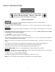
SAFETY INSTRUCTIONS When using chemical feed pumps, basic safety precautions should always be followed to reduce risk of fire, electric shock, and personal injury. Failure to follow these instructions could result in death or serious injury. READ ALL INSTRUCTIONS *** : Secure chemicals and metering pumps, making them inaccessible to children and pets. *** DO NOT PUMP FLAMMABLE LIQUIDS. *** Do not cut the plug or ground lug off the electrical cord.
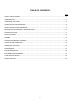
TABLE OF CONTENTS Page SAFETY INSTRUCTIONS ............................................................................................................................... 2 INTRODUCTION.............................................................................................................................................. 4 UNPACKING THE PUMP ................................................................................................................................ 5 PRECAUTIONS FOR OPERATION ......
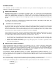
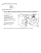
INTRODUCTION These installation, operation and maintenance instructions cover your electronic metering pump. Refer to the pump nameplate to determine the actual model. PRINCIPLE OF OPERATION Diaphragm metering pumps are used to dispense chemicals or fluids. This is achieved by an electromagnetic drive mechanism (solenoid) which is connected to a diaphragm.
EUROPEAN TECHNICAL FILE LOCATION PO Box 91 Washington NE37 1YH United Kingdom UNPACKING THE PUMP Check all equipment for completeness against the order and for any evidence of shipping damage. Shortages or damages should be reported immediately to the carrier and to the seller of the equipment. The carton should contain: - Metering Pump - Clear Flexible Suction Tubing* - Stiff White Discharge Tubing* - Foot valve/Strainer Assy.* - Backpressure Injection Valve Assy.
PRECAUTIONS FOR OPERATION Each Electronic Metering Pump has been tested to meet prescribed specifications and safety standards. Proper care in handling, installation and operation will help in ensuring a trouble free installation. Please read all these cautionary notes prior to installation and start-up of your metering pump. 1. Important: Pump must be installed and used with supplied back pressure/injection valve. Failure to do so could result in excessive pump output flow. 2. Handle the pump with care.
17. When using pump with pressurized systems, make sure the pressure of the system does not exceed the maximum pressure rating on the pump nameplate. Be sure to de-pressurize system prior to hook up or disconnecting the metering pump. 18. Electronic power modules are equipped with automatic reset thermal overload devices and may reset unexpectedly. 19. The pump is designed to operate using a backpressure/injection valve.
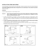
INSTALLATION, PIPING AND WIRING The metering pump should be located in an area that allows convenient connections to both the chemical storage tank and the point of injection. The pump is water resistant and dust proof by construction and can be used outdoors, however do not operate submerged. Avoid continuous temperatures in excess of 40°C (104°F). To do otherwise could result in damage to the pump. MOUNTING Typical mounting arrangements are shown in Figures B to E.
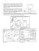
3. The pump can be mounted to a wall as shown in Figure D. A wall mount bracket kit is available which includes all necessary hardware to mount the pump to the wall. Mounting the pump other than as shown in Figure D defeats the purpose of the housing drain. Mounting dimensions for the pump are provided in Figure F for reference. 4. The pump can be mounted on top of a solution tank as shown in Figure E. Install chemical pump on the cover.
PIPING 1. Use provided tubing of specified size for connection. Connect tubing securely to prevent leakage of chemical and the entrance of air. Since plastic nuts are used for fittings, they should not be tightened excessively i.e. hand tighten only. NPT suction and discharge valves must NOT be over tightened. Hold fittings in place while adding piping and fittings. NPT suction and discharge valves should only be tightened 25 to 35 in. lbs. (4.46 to 6.25 kg/cm). 2.
WIRING 1. : Risk of electrical shock. This pump is supplied with a three prong grounding type power plug. To reduce risk of electric shock, connect only to a properly grounded, grounding type receptacle. 2. The metering pump should be wired to an electrical source which conforms to those on the pump nameplate. (Applying higher voltage than the pump is rated for will damage the internal circuit.) 3.
DESCRIPTION OF CONTROLS AND OPERATION INTRODUCTION The pump performs the following functions: Selected Controls - Fixed Rate - External Pulse - Straight Pulses - Pulse Storage - Division - Multiplication - External Current Signal - 4-20 mA - 20-4 mA - Stroke Counting - Timed Operation (intervals) Display Alarms - Circuit Failure - Signal Loss - Full Count - Pulse Overflow - Pulse Rate High Relay Output (one selected at a time) - Relay Off - Pulse Overflow - Stop Function - Repeat Strokes - Current Signal
HELPFUL HINTS You can always get to where you want to go simply by accepting or rejecting choices presented. If you find yourself within a menu where you don't want to be, keep selecting No until you return to the main menu. If you go past the desired selection by mistake, keep selecting No and the pump will take you back to it. A partly flashing display requires your response. A flashing question mark requires a Yes or No answer. Flashing arrows require an Up or Down numerical adjustment.
EXTERNAL PULSE CONTROL - MULTIPLICATION The pump operates as described previously except that incoming pulses are multiplied by a value from 1 to 999 prior to actuating the pump and then worked off at a selected stroking rate. For example, at a multiplier of 5 and a stroking rate of 25%, each incoming pulse causes the pump to stroke five times at 25% stroking rate and then stop. During operation, the display shows the present value and the present count on a running basis.
RELAY OFF In all control options the relay remains open at all times. STOP FUNCTION In all control options the relay is normally open and closes while the Stop Function is activated through the stop port. CURRENT SIGNAL LOSS In any Current Signal control option, the relay is normally open and closes while the Signal Loss alarm is in effect. FULL COUNT In the Stroke Counting control option, the relay is normally open and closes while the Full Count alarm is in effect.
CONTROL REFERENCE SUMMARY CONTROL OPTIONS Fixed Rate Fixed Rate 100% External Pulse Straight Straight Pulse Pulse Storage option Pulse-Store 9999 Pulses ) 999 Division Pulse Storage option: Multiplication ) 999 Store 999 x999/999 Pulse Storage option x999 Store 999 External Current Set High Rate Hi Rate 100% Set Low Rate Low Rate 100% Set High Signal Hi Sig 20.0mA Set Low Signal Low Sig 4.0mA Calibration Sig:xx.x Cal:xx.
SETTINGS OPTIONS Settings? Flow Verify? Yes=On No=Off Relay Output? Relay-Stop? Relay-Repeat? Rel-No Signal? Rel-Full Count? Relay-Overflow? Relay-Failure? Rel-Flow Vrfy? Relay-Off? Factory Init? Init Settings? Are You Sure? Volume-Units? Units = GPD? Units = LPD? Units = LPH? Reset Totals? Are You Sure? Calibrate Flow? Stroke = 100 Run Calib? Language? English? French? German? Spanish? 17
START UP AND OPERATION POWER All metering pumps are available in 115 volts at 50/60 Hertz, single phase. Optionally 230 volts at 50/60 Hertz, single phase can be provided. Prior to start-up always check to insure that the pump voltage/frequency/phase matches that of the power supply. : If pump is fitted with a PVC pump head (7th position of model number is “V”. Note: PVC is gray, not black), uniformly hand tighten the four head screws before use (18-22 inch pounds / 3.21-3.93 kg/cm).
STROKE LENGTH ADJUSTMENT Stroke length can be controlled within 0 to 100% of the diaphragm displacement. (It should be controlled within 20 to 100% for practical use.) Stroke length can be set by means of the stroke length adjusting knob while the pump is in operation. Do not turn the knob while the pump is stopped. Controlling Procedure (for fixed rate): Proper set points for stroke length should be determined after consideration of the pump and characteristics of the fluid.
OPERATION BY EXTERNAL INPUT SIGNALS: The pump can be controlled by three types of input signals. All are fully isolated from AC input power and from Earth ground. The input socket connections are located at the bottom of the control panel face and the signal cords are provided with the pump. Remove rubber plugs to access plug sockets. Stop Function: Operation of the pump can be stopped by an external signal input.
The pump responds to a 4-20mA signal as follows when the high rate is 100%, the low rate is 0%, the high signal is 20mA and the low signal is 4mA. (Figure O below shows straight response) 4-20 mA Signal 20 18 14 12 10 DC mA 16 8 6 0% 25% 50% 75% 4 100% Pump Speed Figure N The pump responds to a 20-4mA signal as follows when the high rate is 0% the low rate is 100%, the high signal is 20mA and the low signal is 4mA.
OUTPUT RELAY Each pump has the option of being provided with one of two separate normally open output relay options as described below. Relays close according to the option selected, and remain closed during the condition specified for the selected option except for the Repeat Strokes option. The Signal Level output relay option is via the output signal terminals on the pump control panel. It is designed to provide direct or inverted voltage output signals as shown in figure O.
ADDITIONAL SETTINGS: “Flow Verify?” – used in conjunction with the flow verification meter; to activate this option: Choose: “Settings?”, press “YES” “Flow Verify?”, press “YES” “Yes=On No=Off?”, press “YES” NOTE: Enabling flow verification on a pump with no flow meter will cause a flow failure.
MAINTENANCE : Before performing any maintenance or repairs on chemical metering pumps, be sure to disconnect all electrical connections and insure that all pressure valves are shut off and pressure in the pump and lines has been bled off. Always wear protective clothing, gloves and safety glasses when performing any maintenance or repairs on chemical metering pumps. ROUTINE MAINTENANCE 1. Routinely check the physical operating condition of the pump.
DIAPHRAGM REPLACEMENT Refer to drawings in the back of the manual. 1. When replacing the diaphragm, it’s always a good idea to replace the valve cartridges and other worn parts. A kit is available from your supplier with all parts necessary to completely rebuild your pump’s wet end. All your supplier needs to know is the “KOPkit No.” on your pump’s nameplate to supply this kit. 2. Set pump stroke length to 0% and unplug the pump. 3.
TROUBLESHOOTING PROBLEM LOSS OF CHEMICAL RESIDUAL TOO MUCH CHEMCIAL LEAKAGE AT TUBING CONNECTIONS PROBABLE CAUSE 1. Pump setting too low. REMEDY 1. Adjust to higher setting (pump must be operating during stroke length adjustment). 2. Scale at injection point 2. Clean injection parts with 8% muriatic acid or undiluted 3. Solution container allowed to run dry 1. Pump setting too high1. 3. Refill the tank with solution and prime. See start-up and operation section 1.
Specifications Pressure, MAX, PSI/BAR @ GPD/GPH/LPD 300/20 3/.13/11 Capacity, MAX, GPD/GPH/LPD @ PSI/BAR 500/20.8/1890 20/1.4 Reproducibility, % MAX Capacity 2 Viscosity, MAX, CPS (1) 1000 Suction Lift @ 1 CPS, MAX, FT/M @ 3000 CPS 10/3.1 (once primed) 3.5/1.
REPAIR SERVICE Normally following the instructions in the previous sections of the manual will rectify any pump problems. If, however, after following these instructions the pump does not perform properly, it can be returned for repair. Please follow the instructions below: 1. Pump cannot be serviced properly if the original pump nameplate or data contained on the nameplate is not intact. 2.
Keep-On-Pumping kits that can save you time and money! The manufacturer has built a reputation for superior reliability by supplying carefully-designed, highquality equipment. Even the best equipment, however, requires a minimal amount of maintenance. KOPkits are designed to guard against unnecessary downtime and assure you the highest level of efficient and uninterrupted service. KOPkits contain those recommended spare parts which will most likely require normal maintenance.