Electronic Metering Pumps Series C, C+, A+, E, E-DC and E+ PULSAtron PLUS Series T7 Addendum starts on page 17 Installation Operation Maintenance Instruction READ ALL WARNINGS CAREFULLY BEFORE INSTALLING
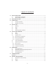
TABLE OF CONTENTS 1.0 SAFETY INSTRUCTIONS ................................................................................................................. 3 1.1 General Safety Considerations ........................................................................................... 3 1.2 Safety Operating Procedures.............................................................................................. 3 2.0 UNPACKING THE PUMP .....................................................................
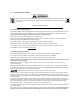
1.0 SAFETY INSTRUCTIONS When using chemical feed pumps, basic safety precautions should always be followed to reduce risk of fire, electric shock, and personal injury. Failure to follow these instructions could result in death or serious injury. READ ALL INSTRUCTIONS 1.1 General Safety Considerations Always wear protective clothing including gloves and safety goggles when working on or near chemical metering pumps.
An air bleed valve is available for most models with tubing connections. Air purges should be performed when the pumpchamber contains no fluid at the time of start-up. As a safety measure, connect the return tubing to the air bleed valve and bypass fluid back to storage tank or a suitable drain. For accurate volume output, the pump must be calibrated under typical operating conditions. Chemicals used may be dangerous and should be used carefully and according to warnings on the label.
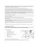
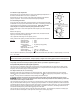
3.0 INTRODUCTION These installation, operation and maintenance instructions cover your electronic metering pump. Refer to the pump data label to determine the actual model. 3.1 Principle of Operation Diaphragm metering pumps are used to dispense chemicals or fluids. This is achieved by an electromagnetic drive mechanism (solenoid), which is connected to a diaphragm.
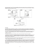
USE AN ANTI-SIPHON VALVE IN THE DISCHARGE LINE whenever the fluid pressure in the discharge line is below atmospheric pressure. This can occur if the injection point is on the suction side of a water pump or against a "negative" head such as when feeding down into a well. 4.2 Piping Use provided tubing of specified size for connection. Connect tubing securely to prevent leakage of chemical and the entrance of air. Since plastic nuts are used for fittings, they should not be tightened excessively (i.e.
A flooded suction (tank liquid level always at a higher elevation than the pump) is recommended when pumping solutions such as sodium hypochlorite (NaOCl), hydrogen peroxide (H 2O2), etc., which are likely to produce air bubbles. Maintaining a low liquid temperature will also help eliminate this problem. Pipe corrosion can result if dilution at the injection point does not occur rapidly.
5.0 START UP AND OPERATION 5.1 Power All metering pumps are available in 115 and 230 volts at 50/60 Hertz, single phase. In addition, certain models are available in 12 volt DC. Prior to start-up always check to insure that the pump voltage/frequency/phase matches that of the power supply. If pump is fitted with a PVC pump head (7th position of model number is “V” or "W". Note: PVC is gray, not black), uniformly hand tighten the four head screws before use, 18-22 in. lbs. (3.2 -3.9 kg/cm).
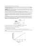
5.3.2 Stroke Length Adjustment Stroke length can be controlled within 0 to 100% of the diaphragm displacement. It should be controlled within 20 to 100% for practical use. Stroke length can be set by means of the stroke length adjusting knob while the pump is in operation. Do not turn the knob while the pump is stopped. 5.3.3 Controlling Procedure Proper set points for stoke length and stroke frequency should be determined after consideration of the pump and characteristics of the fluid.
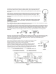
5.5.2 External Pacing Function (E+, A+, C+ and C only) The pump's stroke rate can be controlled by an external signal input. When the input signal line is connected and the EXTERNAL /OFF /MANUAL switch is in the external position and a contact signal is input to the terminal marked , the pump makes one discharge stroke. Operation of more than one pump from the same contact closure will damage the pump circuits.
The signal cord polarity is: Black = Common White = Positive Wrong polarity can result in excess flow. Signal input impedance is 124 ohms. Remove cap from pump socket labeled 4-20 mA, use polarized cord supplied with pump to connect control circuit to pump. Plug cord into pump socket labeled 4-20 mA. 6.
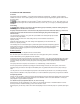
Apply grease to areas of the diaphragm that contact the deflection plate. Slide the diaphragm deflection plate onto the back of the diaphragm stud, radius side towards the diaphragm. Next slide two shims onto the diaphragm threaded stud and screw the diaphragm into the EPM unit. Refer to Figure 14. Turn diaphragm clockwise until deflection plate and shims are tight against solenoid shaft and the diaphragm stops turning.
7.0 TROUBLESHOOTING Problem Probable Cause Remedy 1. Leak in suction side of pump 1. Examine suction tubing. If worn at the end, cut approximately one inch (2.5cm) off and reconnect 2. Valve seats not sealing 2. Clean valve seats if dirty or replace with alternate material if deterioration is noted 3. Low setting on pump 3. When pumping against pressure, the dial should be set above 20% capacity for a reliable feed rate 4. Low suction level 4. Solution must be above foot valve strainer 5.
Leakage at Fitting 1. Loose fittings 1. Tighten hand tight. Replace gasket if hand tightening does not stop leakage 2. Broken or twisted gasket 2. Check gaskets and replace if broken or damaged 3. Chemical attack 3. Consult your pump supplier for alternate material 1. Dirty check valve 1. Remove and replace or clean off any scale or sediment 2. Ball checks not seating or not sealing properly 2. Check seat and ball checks for chips, clean gently.
Appendix A 15
8.0 POLICIES AND PROCEDURES 8.1 Manufacturers Product Warranty The manufacturer warrants its equipment of its manufacture to be free of defects in material or workmanship Liability under this policy extends for twenty-four (24) months from the date of purchase or one (1) year from date of installation or whichever comes first. The manufacturer’s liability is limited to repair or replacement of any device or part, which is returned, prepaid, to the factory and which is proven defective upon examination.
PULSAtron PLUS Series T7 Addendum
PULSAtron PLUS Series T7 Addendum
PULSAtron PLUS Series T7 Addendum
PULSAtron PLUS Series T7 Addendum
PULSAtron PLUS Series T7 Addendum
PULSAtron PLUS Series T7 Addendum
PULSAtron PLUS Series T7 Addendum