Adam Equipment PGL SERIES (P.N.
Easy Reference: Model name of the scale: Serial number of the unit: Software revision number (Displayed when power is first turned on): Date of Purchase: Name of the supplier and place: 2|Page © Adam Equipment Company 2008
CONTENTS 2.0 3.0 INTRODUCTION ....................................................................................5 SET UP...................................................................................................6 3.1 3.2 3.3 3.4 4.0 5.0 UNPACKING AND SETTING UP YOUR SCALE .................................................6 ASSEMBLING THE BALANCE (PGL 203 to PGL 8001)......................................6 LEVELLING THE BALANCE.....................................................................
|Page © Adam Equipment Company 2008
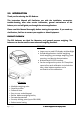
2.0 INTRODUCTION Thank you for selecting the PGL Balance. This Instruction Manual will familiarize you with the installation, accessories, trouble‐shooting, after sales service information, general maintenance of the balance, etc. and will guide you through the various applications. Please read this Manual thoroughly before starting the operation. If you need any clarifications, feel free to contact your supplier or Adam Equipment.
3.0 SET UP 3.1 UNPACKING AND SETTING UP YOUR SCALE Remove the balance from the packing by carefully lifting it out of the box. Inside the box you will find everything needed to start using the balance‐ 9 9 9 9 3.
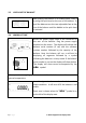
3.3 LEVELLING THE BALANCE After placing the balance in a suitable place, level it by using the spirit level on the rear of the balance. To level the balance turn the two adjustable feet at the rear of the balance until the bubble in the spirit level is centered. 3.4 WARM‐UP TIME Attach the power supply cable to the connector on the rear of the balance. Plug the power supply module into the mains.
3.5 LOCATING AND PROTECTING YOUR SCALE In order to keep your scale functioning at its best we suggest that you do the following: Avoid extremes of temperature. Do not place in direct sunlight or near air conditioning vents. Make sure the scale is located on a strong table and free from vibration. Avoid unstable power sources. Do not use near large users of electricity such as welding equipment or large motors. Use only the factory approved power adapter supplied with the machine.
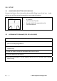
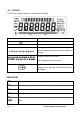
4.0 DISPLAY The LCD has unique symbols to indicate the following: Î0Í Zero Stable Net Net weight A bar graph indicating the proportion of the balance capacity being used by the weight on the pan Symbols shown for the units g, kg, ct, oz, lb, ozt, GN, dwt, dr, tl H, tl T, tl S, MM, T, ti, N, g/cc, Pcs, %, M, and S Not all weighing units are used Low Battery symbol. On when the battery voltage is low, signaling the battery should be recharged.
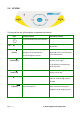
5.0 KEYPAD The keypad has the following keys to operate the balance.
5.
6.0 BASIC OPERATION 6.1 INITIALISATION 1) When the balance is first switched on, it will display the balance serial number (if set), software revision, model capacity and then all segments on the display will be shown. Overall the time taken is usually 5 ‐10 seconds. 2) If a passcode has been set, the display will show “PASSCODE” and the main display will show a zero. In this case you must enter the passcode to continue using the numeric entry method (see section 5.1).
6.2 PASSCODES If a passcode has been set to limit access to the weighing functions of the balance the display will show “PASSCODES” with the main digit set to zero. The display will change to show 7 digits set to zero with the rightmost digit flashing. Use the numeric entry method (see section 5.1) to enter the code. Make sure to enter the correct passcode to continue. See the Section 12.6 for details. 6.
6.4 WEIGHING UNITS You can select alternative weighing units to display the weight by pressing the [Unit] key. The common weighing units are: Unit Symbol Conversion Factor 1g = Conversion Factor 1 unit = grams Grams Kilograms Carat Ounces Pounds Troy ounces Grains Pennyweights Newtons Custom g kg ct oz lb ozt GN dwt N Custom 1 0.001 5 0.035273962 0.0022046 0.032150747 15.43236 0.643014865 0.00980665 As specified 1.0 1000 0.2 28.349523 453.5924 31.103476 0.0647989 1.555174 101.
7.0 FUNCTIONS When weighing, the user can access the applications that have been enabled (see section 12.2). • • • • • Weighing Parts counting Percent weighing Check weighing Density determination The selectable functions can be enabled using a similar method to the Units above by turning the functions on or off. 7.
8) During parts counting checks will be made to determine that the weight of the reference parts is large enough for reasonably accurate counting (weight of each piece should be > 1d) 7.2 PERCENT WEIGHING Percent weighing will be done by defining a certain weight to be 100%. The weight to be used can either be entered by the user or taken from a sample.
12) Place unknown sample to display the percentage weight 13) To perform percent weighing with another sample press [Mode] and continue from step 2 above. 14) To return to normal weighing, press [Mode] then press [Esc]. Note: Percentage will be displayed to the maximum number of decimal places based on the resolution of the balance. To increase or decrease by one decimal place, press the [Up] or [Down] key respectively. 7.
weighing unit. If the weighing unit is pounds: ounces the limit is set in decimal pounds, 1.500 lb = 1 lb 8oz. 4) Press [Enter] to proceed 5) If the “LOW LIMIT” was set to “OFF” or the setting of the low limit is complete, then the display will change to “HIGH LIMIT”.
7.4 DENSITY DETERMINATION It is possible to determine the density of solids or liquids using this mode. The user selects the type of density to be determined and then enters values to be used by the balance. The density mode allows the user to use a special Density Kit or use the below pan weighing facility to perform the necessary weighing. DENSITY OF SOLIDS To perform the density of solids test, the user must have a method to immerse the sample in the chosen liquid.
9) The balance will request the weight of the sample in air by displaying “AIR WEIGHT”. Place the item on the pan or receptacle, if the density kit is used. Press [Enter] to determine the value 10) After completion of the air weighing, the balance will request the weight in liquid by displaying “LIQUID WT”. Submerge the item in the liquid and press [Enter] to start the liquid weighing.
7) The balance will request the weight in air by displaying “AIR WEIGHT”. Place the glass plumb supplied with the density determination kit in air on the weighing pan and press [Enter] to start the air weighing 8) On completion of the air weighing, the balance will request the weight in liquid by displaying “LIQUID WT”. Submerge the glass disk in the liquid and press the [Enter] key. The balance will compute the density of the liquid and display it.
8.0 CALIBRATION The PGL series can only be calibrated with an external mass. 8.1 MANUAL CALIBRATION Pressing the [Cal] key will start calibration. Calibration can also be called for after a set time period as determined by the user (see section 12.5). Calibration using External Calibration mass: 1) Pressing [Esc] will abort the calibration at any time 2) Check the display is at zero.
7) Place the mass on the balance. Press [Enter] to continue 8) On the PGL 203 and PGL 303 models the display will show the busy symbol and after calibration is complete it will show “LOAd 0” on the display. Remove the weight. The scale will return to weighing. 9) All other models will return to weighing as soon as calibration is complete. 8.
8.4 CALIBRATION REPORT The calibration report will show the details from the balance and give the user a place to sign showing he did the calibration. CALIBRATION REPORT Ser No: AE435402 ID No: 123321 Date: 05/03/2008 Time: 18:41:57 Cal: External Mass: 2000g The data for the form will be preceded by a start‐of‐ text character (02H) and terminated with an end‐of‐transmission character (04H).
9.0 RS‐232 INTERFACE The balances have the ability to send or receive data over the serial interface. The weighing data can be sent over the interface either automatically or when the user presses the [Print] key. The user has control over what data is to be printed. The following gives a description of the RS‐232 interface. 9.1 HARDWARE The RS‐232 interface is a simple 3 wire connection.
If output on demand is selected, the user may optionally configure the serial output as a choice of 3 styles of form, either in a default format or in one of two custom formats. Each of the custom formats can be configured to output up to 15 lines of data. The data types that can be printed are: NAME TEXT PRINTED ID number Serial number Date Time Net weight Gross weight Tare weight Unit weight Count Reference weight Percent Checkweigh lower limit Checkweigh upper limit A blank line printed ID no.
9.2 STANDARD FORMAT The balance will print the following data as the standard form. The standard form cannot be changed. The format of the custom forms #1 and #2 will be the same as the standard form until modified by the user.
Basic Input Commands: !KT Tares the balance to display the net weight. This is the same as pressing the [Zero / Tare] key when the balance is in the normal weighing mode. !KP Transmits data over RS‐232 interface. This is the same as pressing the [Print] key when the balance is in the normal weighing mode.
10.0 BATTERY OPERATION The scale may operate from a built in lead acid battery. During operation with the battery the backlight should be disabled for best battery life. Typical battery life 20 hours. If possible disable the backlight automatically if the external power supply is not turned on. 11.0 ERROR CHECKING During weighing the balance is constantly checking to see if the balance is operating within the limited parameters.
12.0 SUPERVISOR MENUS Pressing the [Setup] key while in normal weighing gives access to the menus. 1) When [Setup] is pressed and passcodes are not enable the display will show the message “SUPERVISOR”.
12.2 ENABLE WEIGHING MODES Same steps are followed to enable or disable the weighing modes. 1) Press [Enter] when “MODES” is displayed. The display will show the first mode i.e., Parts Counting (“PARTS”) together with its enabled state “OFF” or “On”. The user can enable or disable the parts counting mode by using [Up] or [Down]. Pressing [Enter] will confirm the setting and will advance to the next weighing mode.
Format of custom forms #1 and #2 If FORM1 or FORM2 is selected, it can be changed by the user using a selection of available data. By default the 2 forms are the same as the standard form unless changed by the user as below. When FORM 1 or FORM 2 is selected the user can set the information to be printed on each line of the form. Pressing the [Up] or [Down] keys will cycle through the options available.
The next line shows: “LINE NO 2” “TIME” ‐ prints time Only one item can be entered per line. Continue until the formatting of the form is complete. There are 15 lines of possible data. After the 15th line has been set or “END” has been selected, the balance will return to the RS‐232 Sub‐menu. Press [Mode] to advance to setting of the next menu or press [Esc] to return to normal weighing. 12.4 SETUP PARAMETERS The user parameters that control the balance are shown under the SETUP.
1) Use the [Up] and [Down] keys to increase or decrease the value for setting. Press [Enter] to accept the setting and advance to the next item in the menu 2) Press [Mode] to advance to setting of the next parameter or [Esc] to return to normal weighing 12.5 CALIBRATION SETUP This menu allows the user to set the calibration parameters.
12.6 PASSCODES To enable the security features in this balance it is necessary to set passcodes. There are 2 passcodes called Operator Passcode and Supervisor Passcode. The Operator Passcode allows an authorised user to operate the basic weighing functions of the balance but will not allow access to the Supervisor Menus if the Supervisor Passcode has been set. To change or disable a Passcode it will be necessary to enter the current passcode.
13.0 SPECIFICATIONS Maximum Capacity Readability Repeatability (s.d.) Linearity ± Pan Units of Measure Functions Overall (wxdxh) PGL 203 PGL 303 200 g 300 g 0.001 g 0.001 g 0.002 g 0.003 g 0.004 g 0.006 g 145 x 125 mm / 5.7 “ X 7.6” grams, milligram, carat, grains, Newtons, troy ounce, pennyweights, ounce, and custom Weight, percent weighing, parts counting, check weighing , density determination Dimensions 251 × 358 × 104 mm 9.9” x 14.1” x 4.
PGL 10001 10 kg 0.1 g 0.2 g 0.4 g Maximum Capacity Readability Repeatability (s.d.) Linearity ± Pan 400 x 300 mm 15.7” x 11.8” grams, kilograms, carat, grains, Newtons, pounds, ounces, pound:ounce, and custom Units of Measure Functions Overall (wxdxh) PGL 20001 20 kg 0.1 g 0.2 g 0.4 g Weight, percent weighing, parts counting, check weighing , density determination Dimensions 455 × 400 × 95 mm 17.9” x 15.7” x 3.7” Net Weight 6 kg / 13.2 Lb.
14.0 WARRANTY STATEMENT Adam Equipment offers Limited Warranty (Parts and Labor) for the components failed due to defects in materials or workmanship. Warranty starts from the date of delivery. During the warranty period, should any repairs be necessary, the customer must inform the supplier or Adam Equipment. The company or its authorised Technician reserves the right to repair or replace any components at its own discretion.
Manufacturer’s Declaration of Conformity This product has been manufactured in accordance with the harmonised European standards, following the provisions of the below stated directives: Electro Magnetic Compatibility Directive 2004/108/EC Low Voltage Directive 2006/95/EC Adam Equipment Co. Ltd. Bond Avenue, Denbigh East Milton Keynes, MK1 1SW United Kingdom FCC COMPLIANCE This equipment has been tested and found to comply with the limits for a Class A digital device, pursuant to Part 15 of the FCC Rules.
ADAM EQUIPMENT is an ISO 9001:2000 certified global company with more than 35 years experience in the production and sale of electronic weighing equipment. Adam products are predominantly designed for the Laboratory, Educational, Medical, retail and Industrial Segments.