Instruction Manual Series HH Electronic Metering Pumps ! ! Carefully read and understand all precautions before installing or CAUTION CAUTION servicing any metering pump.
Contents 1.0 2.0 3.0 4.0 5.0 6.0 7.0 8.0 9.0 10.0 11.0 2 Introduction ................................................................ 4 1.1 Spare Parts ........................................................... 4 Unpacking ................................................................ 5 HH9 Features ................................................................ 6 How to Interpret the Model Number ............................... 7 Pre-Installation Instructions ....................................
12.0 External Control Modes HH9 ........................................ 12.1 Programming Pulse Divide .................................. 12.2 Programming Pulse Multiply ................................ 12.3 Programming mA Response ............................... 12.4 Programming Points 1&2 (SPM) ......................... 12.5 Programming Points 1&2 (SPH) .......................... 13.0 Advanced Features and the Setup Menu HH9 ............. 13.1 Accessing the Setup Menu ..................................
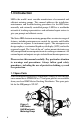
1.0 Introduction LMI is the world’s most versatile manufacturer of economical and efficient metering pumps. This manual addresses the installation, maintenance and troubleshooting procedures for the HH Series manually and externally controlled pumps. LMI has a worldwide network of stocking representatives and authorized repair centers to give you prompt and efficient service.
2.
3.0 HH9 Features Stroke frequency adjustment from 0 SPH (strokes per hour) to 100 SPM (strokes per minute). Internal (manual) or external mode select. Flexible slope adjustable response to mA input signals. Divide or multiply (batch) incoming pulses (1 to 999). Batch accumulate option. Integral blowdown controller feature. Keypad locking. Low-level shutoff with alarm output. 6-level pressure control. Continuous non-volatile memory (EEPROM)--no battery required. Remote ON/OFF control. Pulse (pacing) output.
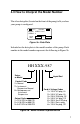
4.0 How to Interpret the Model Number The silver data plate (located on the front of the pump) tells you how your pump is configured. 115 V.A.C. 50/60 HZ. 1.4 A MODEL # HH931-987 SERIAL # MAX/ GPH 0.07 PSI 1000 Figure 3a : Data Plate Included on the data plate is the model number of the pump. Each number in the model number represents the following in Figure 3b.
5.0 Pre-Installation Instructions ! CAUTION Specific precautions should be taken when working with all LMI metering pumps. Please read this section carefully prior to installation. Protective Clothing ! CAUTION ALWAYS wear protective clothing, face shield, safety glasses and gloves when working on or near your metering pump. Additional precautions should be taken depending on the solution being pumped. Refer to MSDS precautions from your solution supplier.
Electrical Connections ! CAUTION WARNING: to reduce the risk of electrical shock, the metering pump must be plugged into a grounded outlet with ratings conforming to the data on the pump control panel. The pump must be connected to a good ground. DO NOT USE ADAPTERS! All wiring must conform to local electrical codes. 6.0 Installation Instructions The minimum allowable system pressure for the HH pump is 200 psi. If your system operates at a lower pressure, a back pressure valve must be installed. 6.
6.2 Pump Mounting The HH pump requires a Flooded Suction installation. The pump should be securely mounted at the base of the storage tank with the suction piping sloping downward to the pump. All piping should be cleaned and blown-out prior to connection to the HH pump. 6.3 Plumbing ! CAUTION Always adhere to local plumbing codes and requirements. Be sure the installation does not constitute a cross connection. Check your local plumbing codes for guidelines.
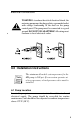
The discharge piping must be installed and supported so that it does not place a supportive load on the liquid end. ! CAUTION Series HH pumps are capable of developing 1000 psi of discharge pressure. All piping must have sufficient rating to withstand maximum pressure. For calibration purposes, it is recommended that a 200 mL graduated cylinder be piped in-line, on the suction side of the pump (see Figure 4). TANK 25ml Cylinder Figure 4: Series HH Recommended Installation. 6.
6.5 Priming and Operation LMI performance tests every pump prior to shipping to insure that it meets the design parameters. This test is performed using water. Please be advised that the pumps are shipped with water in the Liquid End. If it is incompatible with the chemical that is being injected, the head must be dried. When all of the previously mentioned precautions and safety regulations required by your facility or local ordinances have been considered, you may start priming your pump.
7.0 Output Adjustment Controls Once the pump is primed, the output must be adjusted to meet the requirements of the system. This adjustment is made by varying both the stroke and speed of the pump. 7.1 Pressure Control Adjustment (HH9 Only): The pressure control adjustment, unique to LMI, allows for the fine tuning of your HH9 Pump. This reduces over pumping of chemical and power consumption while increasing the accuracy and life of your pump.(See Section 11.3) 7.
7.3 Stroke Adjustment: The Stroke Adjustment dial controls the volume of chemical being injected with each stroke. The 100% setting indicates the maximum volume per stroke. The maximum rated output of your pump is indicated on the data plate. The HH output control features have been designed to make it easy for the user to determine the appropriate speed and stroke settings. 7.4 Calibration The HH has been designed to inject a precise, repeatable amount of chemical against system pressure.
8.0 Accessories 8.1 8-Pin Cable ( P/N 33738 HH9 Only) The 8-pin external cable assembly can be used to control stroke frequency in response to a 0 to 20 mA or 4 to 20 mA instrument signal. This cable assembly also provides output signals for pacing (pulse output), alarm (general) and computer alarm.
8.2 Optional 4-Pin Cable (P/N 33796 HH9 Only) The optional 4-pin external cable is used for connecting incoming pulse or pacing signals such as those triggered by a manual switch, reed switch, opto-coupler or by NPN or PNP transistors. The remote ON/OFF input is also accessed through the standard 4-pin connector.
8.4 Optional "Hall Effect" Cable (P/N 33833) An optional cable assembly is available for pacing your pump directly from an LMI Flowmeter fitted with a Hall Effect sensor. This cable connects to the Flowmeter as shown in Figure 8 (There is no need for a Programmable Divider; its function is built into the pump).
9.0 Checking Pump for Proper Zero Position (Stroke Knob) 1.With pump running, turn stroke knob counter-clockwise toward zero or end of black or red band on dial. 2. LISTEN to the clicking as the pump is running. The pump should operate quietly at the zero position (no clicking). 3. If the pump continues to click at zero or stops clicking before zero is reached, the pump zero must be reset. 9.1 Push on Knob Re-Zeroing and Stroke Knob Disassembly and Assembly 1.
Figure 9: Stroke Knob Assembly 19
10.0 Keypad/Display: Description and Function (HH9 Only) mA EXT X : INT FLOW P12 MIN Figure 10: HH9 Keypad 10.1 LCD Screen The LCD screen is the window in which all values and menu choices are displayed (see Figure 11).
10.2 Start/Stop STOP START The STOP (Start/Stop) key turns the pump on or off. If the pump START is not running, pressing this key will cause the pump to start running. The symbol appears on the display while the pump is running. Each time the pump strokes, the symbol clears. If STOP the pump is running, pressing the S T A R T (Start/Stop) key will stop the pump. 10.
11.0 Operation of the Series HH9 These pumps feature EEPROM nonvolatile memory. The pump will always power up in the last used mode. When shipped from the factory the pump will power up in the "Internal" (manual) mode, with the pump OFF and a speed setting of 100 SPM. If the power to the pump is cut less than 15 seconds after the last programmed values have been set, the latest changes will NOT be stored in nonvolatile memory.
11.2 Speed The speed may be changed with the pump ON or OFF. To increase or decrease the speed, press or hold the (Up) or (Down) key. The range runs from 0 SPH to 100 SPM. While normally the speed will be set in SPM, if settings of SPH are desired, hold the (Down) key until the display reads 0, then continue to hold it for an additional three (3) seconds. The display will then show H60, which is 60 SPH. The speed can be further reduced to 0 SPH with the (Down) key.
11.3 Pressure Level Control The maximum pressure rating of your pump can be adjusted to reduce pulsation shock in your discharge line. The pumps have a 6point pressure control scale. The minimum setting is 0 and the maximum is 5. To access the pressure setting, press the MODE I E X T N T (Mode) key and (Up) key at the same time and hold for two (2) seconds. The current pressure setting may be altered using the (Up) or (Down) keys.
11.5 Low-Level Switch (P/N 29190) When the Low-Level Switch is fitted to the pump and a fault condition exists, the "E1" error code will flash on the LCD screen INT MIN . For more information on the Low-Level Switch, see the LowLevel Switch Assembly information sheet (P/N 1368). When a fault condition exists, the pump is stopped and the alarm and computer alarm lines are activated to allow remote monitoring. After clearing the fault (by filling the tank), the pump will automatically restart. 12.
External Mode Select: Pulse Divide, Pulse Multiply, and mA Response Any of three external modes may be selected when the pump is stopped by pressing and holding the (Mode) key and (Start/Stop) key for five (5) seconds, then releasing. As noted above, the default is Pulse Divide. Pressing and releasing these keys brings you to the Pulse Multiply mode . In this mode, the LCD screen alternates between the pulse multiply value and OFF.
12.2 Programming the Pulse Multiply (Batch) Value The multiply value is altered by using the (Up) and (Down) keys to change the value. The pump must be OFF and in the External Multiply mode. Like the divide value, the valid range for the multiply value runs from 0 to 999 pulses. When the pump is ON, a single external pulse will initiate a batch of pump strokes. The number of remaining pulses are displayed on the LCD screen . When 0 is reached, the display resets to the multiply value.
Batch Accumulate The Batch Accumulate function allows you to opt to have any extra input pulses received in the multiply mode accumulate up to a maximum batch of 999. If Batch Accumulate is enabled and a pulse is received during the countdown, the programmed multiply value will be added to the current displayed value. Pulses causing the maximum batch of 999 to be exceeded will result in an E4 error message. When Batch Accumulate is enabled, the LCD screen alternates between the current multiply value and .
12.4 Programming Points 1 and 2 (SPM) To program points P1 and P2, first ensure the pump is in the mA mode and OFF. If you wish to program the response in "SPM", switch to the internal mode. The speed must be set to a SPM value . Return to the External mA mode. INT MIN mA P1 MIN P1 and mA P2 P2 100 SPM P2 MIN . 50 0 .P1 4 12 20 mA Figure 12 Press either the (Up) or (Down) key. The LCD screen will display . After five (5) seconds, the display will show the mA value for P1 .
Figure 13 If the mA input goes below the value programmed for P1 or above the P2 value, the response will "plateau," as indicated by the dotted lines above. The valid input range is from 0.5 to 21 mA. Below 0.5 mA, the pump will be off. Above 21 mA, the E5 error code will be displayed intermittently .
12.5 Programming Points 1 and 2 (SPH) If you wish to program the response in strokes per hour, start by being in the External mA mode. Next, switch to the Internal mode. If the Internal setting is in strokes per minute, change to strokes per (Down) key until the display reads 0 SPM. hour by holding the Continue to hold it for another three (3) seconds. The display will now read SPH . Set the speed to any SPH value (the actual setting has no bearing on mA response). Return to the External mA mode.
Figure 14 The valid input range is from 0.5 to 21 mA. Below 0.5 mA, the pump will be off. Above 21 mA, the E5 error code will be displayed intermittently . When programming strokes per hour, the maximum rate is 60. P1 and P2 must BOTH BE SPM or BOTH BE SPH.
13.0 Advanced Features and the Setup Menu for HH9 Advanced features such as Batch Accumulate, Computer Interfacing, and Automatic Voltage Compensation, may be selected and altered in the Setup Menu of the Series HH9. The following configuration chart describes each menu item, its description, and available settings.
13.1 Accessing the Setup Menu To access the Setup Menu, ensure that the pump is OFF and in the (Up) key, bring the stroke rate to 100 Internal mode. Using the SPM. At this point, keep the (Up) key pressed for five (5) seconds. The LCD screen then displays the current software revision, indicating that you have entered the Menu mode . Press the (Mode) key to scroll through the Menu Items. Use the (Up) or (Down) key to enable or disable menu functions and program values.
13.2.2 Menu Item 3: Automatic Voltage Compensation Menu item 3 enables (1) or disables (0) automatic voltage compensation. This unique feature allows a constant power level to be delivered to the EPU of the pump, even when the voltage of the external power source is fluctuating. This results in smooth pump output in spite of fluctuating voltage and prevents overheating. Automatic voltage compensation becomes active two minutes after power up. 13.2.
13.2.5 Menu Items 7, 8 and 9 Activate the Integral Blowdown Feature These Menu Items will require additional accessories and customer supplied components. This Integral Blowdown feature provides cooling tower control from your LMI microprocessor pump when used in conjunction with a pulse output type flowmeter (batch mode) or 4-20 mA signal (milliamp mode). These signals can then be input into the pump to provide activation of both the pump and a customer supplied solenoid valve.
A. Batch Mode Programming Menu Menu Item 1 Batch Accumulate Select: 0 = (Disable) or 1= (Enable) Menu Item 7 Integral Blowdown: Select 1 = (Enable) Menu Item 8 Solenoid ON time: Select 0 to 255 (Seconds) Select "INT" mode and set the manual strokes per minute. Select "EXT X" (multiply) mode (batch mode) and program stroke count. On receipt of a pulse from the flowmeter, the pump strokes the programmed number of pulses.
14.0 Troubleshooting PROBLEM Pump Will Not Prime Pump Loses Prime 38 POSSIBLE CAUSE SOLUTION 1. Pump not turned on or plugged in. 1. Turn on pump/plug in pump. 2. Output dials not set properly. 2. Always prime pump with speed at 80% and stroke at 100%. 3. Pump suction not flooded. 3. The HH pump requires a flooded suction. Reposition the pump accordingly. 4. Air trap in suction piping. 4. Be sure the suction piping is installed so that there are no air traps (see section 6.2). 5.
Troubleshooting (continued) PROBLEM Leakage at Piping Connection Low Output or Failure to Pump Against Pressure Failure to Run Excessive Pump Output 40 POSSIBLE CAUSE SOLUTION 1. Piping not sealed. 1. Apply Teflon tape to NPT threads and tighten piping (see section 6.3). 2. Worn seal rings. 2. Replace o-rings. Spare Parts (SP-987). 3. Solution attacking Liquid Handling Assembly material. 3. Consult your local distributor for alternate materials. 1.
Appendix A: Input/Output Description 4-Pin Connector Pacing (Pulse) Input / Opto-Isolated Input (HH7 and HH9 Only) Methods of Triggering Pump. Reference: 4-Pin Cable (P/N 33796) (HH9 Only) 4-Pin Cable (P/N 28368) (HH7 Only) Switch NPN Transistor PNP Transistor Pin 1 White Pin 2 Black + Pin 1 White - Pin 2 Black + Pin 1 White - Pin 2 Black Opto Isolator + - Pin 1 White Pin 2 Black HH9 Only Switch or transistor must be capable of switching 2mA at 15 VDC.
HH7 Only Switch or transistor must be capable of switching 2mA at 15 VDC. Minimum time in low impedance state (on) is 50 mSec. Minimum time in high impedance state (off) is 100 mSec. Remote On/Off (Opto-isolated Input) (HH9 Only) Switching this line to ground starts the pump. Releasing this line, stops the pump. The (Start/Stop) key will always override the Remote Start/Stop.
8-Pin Connector (HH9 Only) Analog 0-20 mA Input +0 to 20 mA Violet -0 to 20 mA Green 8-Pin Cable (P/N 33738) This is reverse polarity protected with a 22 Ohm impedance, a resolution or 0.1 mA and an accuracy of +/- 0.2 mA typically. 15 v Output The +15V Output (pin 1 Red) is regulated and capable of delivering 30 mA current. Alarm Output This is an opto-isolated open collector Darlington pair capable of switching 25 mA at +24 VDC to within 1V of ground typically.
Application: Relay Switching +15V Pin 1 Red Load Alarm Output Pin 6 Yellow GND Pin 2 Black Computer Alarm Output This is an opto isolated, open collector output capable of switching 2 mA at +24 VDC to within 0.4V of ground typically. Reference: 8-Pin Cable (P/N 33738) Pin 8 Blue GND Pin 2 Black This output tracks the alarm output (i.e. the conditions for activating and de-activating this output are the same as for the alarm output).
Application: Low Current LED Switching +15V Pin 1 Red 10K Ohms Pin 8 Blue *Low Current LED 1.0 mA = 10 mcd GND Pin 2 Black This is an opto-isolated, open collector output capable of switching 2 mA at +24 VDC to within 0.4V of ground typically. Pacing Output (Opto-isolated Output) Reference: 8-Pin Cable (P/N 33738) Pin 5 Orange GND Pin 2 Black The output transistor turns ON at the start of a stroke and remains ON for approximately 100 mSec.
Appendix B: Summary of Error Messages (HH9 Only) E1 INT MIN is caused by a Low-Level fault with a Low-Level Switch connected to the pump. The pump is stopped and the alarm outputs are activated. This operates in all Internal and External modes. The pump automatically restarts when the fault is cleared. E2 indicates that the pump has lost prime. Again, the pump is stopped and output alarms activated. Item 4 in the Advanced Menu must be disabled (set to 0), it is not usable with the HH9 pump.
201 Ivyland Road Ivyland, PA 18974 USA TEL: (215) 293-0401 FAX: (215) 293-0445 http://www.lmipumps.com ISO 9001 Certified © 2004 LMI Milton Roy - All Rights Reserved Printed in USA Specifications subject to change without notice.