___ Instruction Manual Electronic Metering Pumps ! CAUTION Carefully read and understand all precautions before installing or servicing any metering pump. ! CAUTION For file reference, please record the following data: Model No: Serial No: Installation Date: Installation Location: When ordering replacement parts for your LMI Metering Pump or Accessory, please include complete Model Number and Serial Number of your unit. sales@novatech-usa.com www.novatech-usa.
Contents 1.0 Introduction.......................................................................................... 4 1.1 Spare Parts............................................................................... 4 2.0 Unpacking Check List ......................................................................... 6 3.0 Pre-Installation Instructions.................................................................. 8 4.0 Installation..........................................................................
1.0 Introduction LMI is the world’s most versatile manufacturer of economical and efficient metering pumps. This manual addresses the installation, maintenance and troubleshooting procedures for manually and externally controlled pumps. LMI has a worldwide network of stocking representatives and authorized repair centers to give you prompt and efficient service. Please review this manual carefully. Pay particular attention to warnings and precautions.
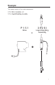
Example: Your pump consists of two main components: 1. The Drive Assembly; and 2. The Liquid Handling Assembly.
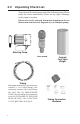
2.0 Unpacking Check List Your carton will contain many or all of the following items. Please notify the carrier immediately if there are any signs of damage to the pump or its parts. Please refer to the enclosed Instruction Supplement for an illustration and electrical diagram of your complete pump. Metering Pump Foot Valve Ceramic Foot Valve Weight Tubing Depending on the model, your carton may contain 0, 1, 2 or 3 rolls of tubing.
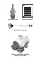
Instruction Supplement LMI MILTONROY Injection Check Valve Instruction Supplement Optional Milliamp Input Cable Optional 4-Function Valve (pictured) or Optional 3-Function Valve 7
3.0 Pre-Installation Instructions The following precautions should be taken when working with LMI metering pumps. Please read this section carefully prior to installation. Precautions ! CAUTION ! CAUTION ! CAUTION 8 Protective Clothing ALWAYS wear protective clothing, face shield, safety glasses and gloves when working on or near your metering pump. Additional precautions should be taken depending on the solution being pumped. Refer to MSDS precautions from your solution supplier.
! CAUTION ! CAUTION Tubing Connections Inlet and outlet tubing or pipe sizes must not be reduced. Make certain that all tubing is SECURELY ATTACHED to fittings prior to start-up (see Section 4.3, Tubing Connections). ALWAYS use LMI supplied tubing with your pump, as the tubing is specifically designed for use with the pump fittings. It is recommended that all tubing be shielded to prevent possible injury in case of rupture or accidental damage.
Electrical Connections To reduce the risk of electrical shock, install only on a circuit protected by a ground-fault circuit-interrupter (GFCI). The metering pump must be plugged into a grounded outlet with ratings conforming to the data on the pump control panel. The pump must be connected to a good ground. DO NOT USE ADAPTERS! All wiring must conform to local electrical codes. WARNING: Do not hook a US style pump plug into a non-US (UK, Aust, NZ or Swiss) wired power system.
4.2.1 Flooded Suction The pump is mounted at the base of the storage tank. This installation is the most trouble-free , and is recommended for very low outputs, solutions that gasify, and high-viscosity solutions. Since the suction tubing is filled with solution, priming is accomplished quickly and the chance of losing prime is reduced. ! CAUTION When pumping downhill or into low or no pressure system, a back pressure/anti-syphon device should be installed to prevent overpumping or syphoning.
4.2.2 Suction Lift - Wall Bracket Mount The pump may be mounted using an LMI Wall Mount Bracket Assembly (part no. 34643) directly above the solution tank. A pump mounted in this manner allows for easy changing of solution tanks or drums. Tee Injection Check Valve LMI Pump Rear Mount LMI Pump Front Mount Solution Tank 2.0 in.
4.2.3 Suction Lift - Tank Mount The pump may be mounted on a molded tank provided there is a recess to keep the pump stationary. LMI 10-gallon tank (part no. 27421), 35-gallon tank (part no. 27400), and 50-gallon tank (part no. 26350) have molded recesses for pump mounting. Pressure Line Tee Injection Check Valve LMI Pump LMI Pump LMI 50 Gallon Solution Tank LMI 10 Gallon Solution Tank Ceramic Weight Foot Valve Foot Valve 2.0 in. (50 mm) Space for Sediment Accumulation 2.0 in.
4.2.4 Suction Lift - Shelf Mount The pump may be mounted on a shelf (customer supplied) maintaining a suction lift of less than 5 ft (1.5 m). An LMI mounting kit (part number 10461) is available for securing the pump to a shelf. Flow Flow Injection Check Valve Anti-Syphon Pressure Relief Valve (Optional Accessory) Solution Drum 2.0 in.
4.3 Tubing Connections 1. Insert tubing through Coupling Nut—Tubing should enter the smaller end of the Coupling Nut first, orienting the larger opening of the Coupling Nut toward the tubing end. 2a. For 1/4” OD tubing: Position the Female Ferrule so that 1/4” to 3/8” (5-10 mm) of tubing protrudes from the Female Ferrule. Orient the raised collar of the Ferrule toward the Coupling Nut (reference FIGURE 1). 2b.
4.4 Multi-Function Valves Your pump may be equipped with one of the following multifunction valves: 3-FV, 4-FV, or standard discharge valve. If your pump is not equipped with a multi-function valve and you feel it is needed in your application, it can be purchased as an accessory. Contact your local LMI stocking distributor. 4.4.1 Three Function Valve (3-FV) 1. 2. 3. 4.4.2 If the discharge line is over pressurized, the valve opens sending solution back to the supply tank.
Flow Flow DO NOT submerge return line in solution LMI 4-FV (Accessory) Prevents syphoning when pumping into suction side of recirculating pump (Vacuum) LMI 4-FV (Accessory) Prevents over pumping and syphoning when pumping downhill into low or no pressure Tank Recirculating Pump LMI Pump Tank Injection Check Valve To Injection Point Typical 4-FV Installation 17
4.5 4-Function Valve Installation • To mount to a pump, remove the discharge fitting from the pump (if present) leaving the cartridges in the pump head. Position the 4FV coupling nut on pump head over cartridges with threads up, and insert 4FV fitting and thread into pump head over cartridges. Tighten the fitting to 50 in-lbs using a 13/16” or 20 mm socket. Insert the large opening on the 4-Function valve into the 4FV coupling nut and hand tighten.
4.6 AutoPrime™ Liquid End Return to Supply TM AutoPrime Valve Discharge Valve Discharge Suction Valve Inlet AutoPrime™ Liquid End AutoPrime™ Pumps installed with the AutoPrime™ Liquid End are equipped with a valve that allows for constant removal of vapors and gasses inherent with effervescent chemicals such as Sodium Hypochlorite and Hydrogen Peroxide. The valve keeps the pump primed automatically.
4.7 Foot Valve/Suction Tubing Installation The Foot Valve acts as a check valve to keep the pump primed in suction lift applications. The foot valve is designed to be submersed in the solution tank or drum and must sit in a vertical position at the bottom. Position approximately 2 inches (50 mm) off the bottom if the tank or drum contains sediment. Pump models equipped with high-viscosity liquid ends are not equipped with foot valves. Flooded suction is recommended.
4.8 Injection Check Valve and Discharge Tubing Installation A. Installing Injection Check Valve (Figure 1) 1. The Injection Check Valve prevents backflow from a treated line. Install the injection check valve at the location where chemical is being injected into the system. 2. Any size Female NPT fitting or pipe tee with a reducing bushing to ½" Female NPT will accept the injection check valve. PTFE tape should only be used on threads that are connected with pipes. 3.
5.0 Liquid End Parts List Reference Liquid End Sheets on LMI Online Library at: www.lmipumps.com. 1. Select “Online Literature Library” in the Navigation Bar on left. 2. Once on Online Literature Library use “Product” drop down to select “Liquid Handling Assemblies.” 3. Select “Gallery” or ”Index” to view Liquid End sheets.
6.0 Start-up and Adjustment a.) The pump is normally self-priming if suction lift is 5 ft (1.5m) or less and the steps below are followed. b.) Pumps are shipped from the factory with water in the pump head to aid in priming. 6.1 Output Adjustment Controls Manual series pump controls are not equipped with pressure control. 1.
6.2 ! Start-Up/Priming for Pump Supplied with Multi-Function Valve Read this entire section completely before proceeding. CAUTION When all precautionary steps have been taken, the pump is mounted, and the tubing is securely attached, you may now start priming the pump. 1. Plug in or switch the pump on. 2. While the pump is running, set the speed knob at 80% and the stroke knob at 100%. If the pump is equipped with pressure control, turn fully clockwise. 3.
6.3 Start-Up/Priming without Multi-Function Valve ! Read this entire section completely before proceeding. CAUTION When all precautionary steps have been taken, the pump is mounted, and the tubing is securely attached, you may now prime the pump. 1. Plug in or switch on the pump. 2. While the pump is running, set the speed knob at 80% and the stroke knob at 100%. If the pump is equipped with pressure control, turn fully clockwise . 3.
6.4 Output Adjustment Once the pump has been primed, an appropriate output adjustment MUST be made. Pump output should be calculated and adjustments made accordingly. 6.5 Total Pump Output Calculate the total output of the pump as follows: PUMP OUTPUT = MAX PUMP OUTPUT x % SPEED x % STROKE Example: P151-392SI Use MAX Output (from dataplate on bottom center of pump control panel) = 24 GPD (24 gallons per day). If the pump is set at 60% speed and 70% stroke length, the approximate pump output is: 24.
7.0 Methods of Externally Triggering Method of Triggering LMI Pump Through 4-Pin Connector 1. Switch Closure Switch closing triggers pump 2. NPN Transistor Base goes high to trigger pump 3. PNP Transistor Base goes low to trigger pump + White – Black + White – Black + White 4. Opto Isolator – Black Switch or transistors must be capable of switching 15V DC at 2 milliamperes. Minimum time in low impedance state (on) is 50 milliseconds. Minimum time in high impedance state (off) is 100 milliseconds.
or Pacing B7, C7 and P7 Pumps 29
8.0 Calibration Once installation is complete and the approximate output has been determined, the pump should be calibrated to adjust speed and stroke for your actual desired output. (Calibration cylinders may be purchased from your local LMI distributor, ref. publication 1798.) . 1. Be sure the pump is primed, and discharge tubing and Injection Check Valve are installed as they would be in normal service (i.e., including factors such as injection pressure, fluid viscosity, and suction lift). 2.
8.1 Pressure Control Adjust Pressure Control: While unit is running, turn Pressure Control Potentiometer slowly counter-clockwise until unit just begins to stall. From this stall point, now turn Pressure Control Potentiometer clockwise halfway between the stall point and maximum setting. This is the optimum pressure control setting for your application. Increase setting if back pressure is increased. Adjusting pressure control decreases pressure rating of pump.
8.2 Calibration Procedure - On-Site Volumetric Calibration in External Mode 1. Since pump output is governed by an external device such as Flowmeter-Pulser, Liquitron™ Controller, or 4-20 mA DC signal from an instrument with an LMI Analog-toDigital Converter, only the output per stroke may be calibrated. 2. With pump primed and discharge tubing connected to the injection point as it would be in normal service, place Foot Valve Assembly in a graduated container with a volume of 1000 ml or more. 3.
! Read steps 1 and 2 below before proceeding. ! Be sure your relief tubing is connected to your multi-function valve and runs back to your solution drum or tank. CAUTION CAUTION 1. 2. 9.2 ! CAUTION Be sure the Injection Check Valve is properly installed and is operating. If a shut off valve has been installed downstream of the Injection Valve, it should be closed. 1/4 turn the black knob on the valve. The discharge line is now depressurized.
If the liquid cannot be pumped due to Liquifram™ rupture using protective clothing, gloves and face shield, carefully disconnect the suction and discharge tubing. Remove the four screws to the head and immerse the head in water or other neutralizing solution. 2. Start the pump. While running, set the stroke knob to zero and turn the pump off. See Section 10.0 for proper zero . 3. With the unit off, unscrew the Liquifram™ by carefully grasping the outer edge and turning it counter-clockwise .
Liquifram™ Stroke Setting Chart Pump Series * Stroke Knob Setting All AA, B, J, P Series C10, C11, C12, C70, C71, C72, C76, C90, C91, C92, E70, E71, E72 90% C78 50% C13, C14, C73, C74, C77, C93, C94, E73, E74 70% Liquifram™ on M Series pumps only, must be bottomed completely (turned all the way in). Do Not Use Straight Edge. 6.
9.3 Cartridge Valves, Seal Rings/Valve Balls and Injection Check Valve Spring Replacement ! CAUTION ALWAYS wear protective clothing, face shield, safety glasses and gloves when working on or performing any maintenance or replacement on your pump. See MSDS information from solution supplier for additional precautions. 1. Refer to the LMI Metering Pump Price List for the proper Spare Parts Kit or RPM Pro Pac™ kit number or contact your local LMI stocking distributor. 2.
IMPORTANT: Note correct orientation of each check valve. 5. ! CAUTION Install the new spring in the Injection Check Valve. Depressurize and drain pipeline (or isolate I.C.V. point using valves) so that I.C.V. can safely be disassembled. 10.0 Checking Pump for Proper Zero Position (Stroke Knob) 10.1 ` 1. With pump running, turn stroke knob counter-clockwise toward zero or end of black or red band on dial. 2. LISTEN to the clicking as the pump is running.
7. Position the outer section of the knob so that the pointer aligns with zero on the nameplate or end of the black or red band. 8. Push down on the outer section (a snap sound indicates parts are locked together). 9. Replace the yellow cap over the outer section of the knob, aligning the tabs on the cap with the slots inside the knob.
11.0 Troubleshooting PROBLEM Pump Will Not Prime Pump Loses Prime 40 POSSIBLE CAUSE 1. Pump not turned on or plugged in. 2. Output dials not set properly. 3. Foot Valve not in vertical position on bottom of tank. 4. Pump suction lift too high. 5. Suction tubing is curved or coiled in tank. 6. Fittings are over tightened. 7. Air trap in suction valve tubing. 8. Too much pressure at discharge. (Pumps without multi-function valve.) 1. Solution container ran dry. 2.
SOLUTION 1. Turn on pump/plug in pump. 2. Always prime pump with speed at 80% and stroke at 100%. 3. Foot Valve must be vertical (see Foot Valve Installation, Section 4.6). 4. Maximum suction lift is 5 ft (1.5 m). Pumps with High Viscosity Liquid Handling Assemblies require flooded suction. 5. Suction tubing must be vertical. Use LMI tubing straightener supplied with pump (see Section 4.6). 6. Do not overtighten fittings.
Troubleshooting (continued) PROBLEM Leakage at tubing POSSIBLE CAUSE 1. Worn tubing ends. 2. Loose or cracked fitting. 3. Worn seal rings. 4. Solution attacking Liquid Handling Assembly material. 1. Low Output or Failure to Pump Against Pressure 2. Failure to Run Excessive Pump Output 42 Pump’s maximum pressure rating is exceeded by injection pressure. Worn Seal Rings. 3. Ruptured Liquifram™. 4. Incorrect stroke length. 5. Tubing run on discharge may be too long. 6.
SOLUTION 1. Cut about 1 in (25 mm) off tubing and then replace as before. 2. Replace fitting if cracked. Carefully hand tighten fittings. Do not use pipe wrench. Once fitting comes into contact with seal ring, tighten an additional 1/8 or 1/4 turn. 3. Replace balls and seal rings (see Section 8.3) Spare Parts (SP-#). 4. Consult your local distributor for alternate materials. 1. Injection pressure cannot exceed pump’s maximum pressure. See pump data plate. 2.
12.