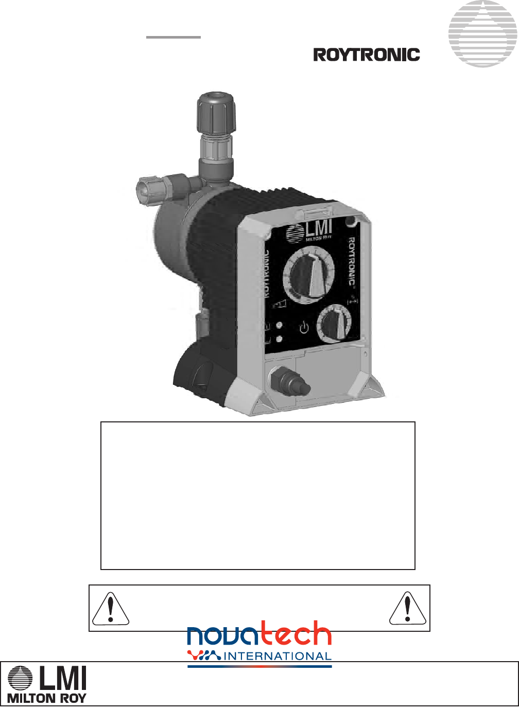
Instruction Manual Series A Electronic Metering Pumps ® For file reference, please record the following data: Model No: _____________________________________ Serial No: _____________________________________ Installation Date: ________________________________ Installation Location: _____________________________ When ordering replacement parts for your LMI Metering Pump or Accessory, please include complete Model Number and Serial Number of your unit.
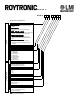
® Series A Model A 7 5 1 - 8 2 8 S I Model Code Configuration Control Code Speed (stroking frequency) fixed and stroke length manually adjustable Speed (stroking frequency) and stroke length manually adjustable External control capability through pulse input and low level float switch plus manual control adjustments of control code 0 Drive External control capability through pulse input and low level float switch plus manual control adjustments of control code 1 External control capability through 4-20 m
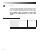
Contents 1.0 2.0 3.0 4.0 5.0 6.0 Precautions . . . . . . . . . . . . . . . . . . . . . . . . . . . . . . . . . . . . . . . . . . . . . . . . . . . . . . . . . . . . . . . . . 4 Introduction . . . . . . . . . . . . . . . . . . . . . . . . . . . . . . . . . . . . . . . . . . . . . . . . . . . . . . . . . . . . . . . . . 6 2.1 Specifications . . . . . . . . . . . . . . . . . . . . . . . . . . . . . . . . . . . . . . . . . . . . . . . . . . . . . . . . 6 2.2 Unpacking Check List . . . . .
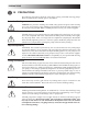
PRECAUTIONS 1.0 PRECAUTIONS The following precautions should be taken when working with LMI metering pumps. Please read this section carefully prior to installation. Protective Clothing ALWAYS wear protective clothing, face shield, safety glasses and gloves when working on or near your metering pump. Additional precautions should be taken depending on the solution being pumped. Refer to MSDS precautions from your solution supplier.
PRECAUTIONS Plumbing Always adhere to your local plumbing codes and requirements. Be sure installation does not constitute a cross connection. Check local plumbing codes for guidelines. LMI is not responsible for improper installations. Back Pressure/Anti-Syphon Valve If you are pumping downhill or into low or no system pressure, a back pressure/antisyphon device such as LMI’s Four-Function Valve should be installed to prevent overpumping or syphoning. Contact your LMI distributor for furthur information.
INTRODUCTION 2.0 Introduction LMI is the world’s most versatile manufacturer of economical and efficient metering pumps. This manual addresses the installation, maintenance and troubleshooting procedures for manually and externally controlled pumps. LMI has a worldwide network of stocking representatives and authorized repair centers to give you prompt and efficient service. Please review this manual carefully. Pay particular attention to warnings and precautions.
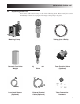
UNPACKING CHECK LIST 2.2 Unpacking Check List Your carton will contain many or all of the following items. Please notify the carrier immediately if there are any signs of damage to the pump or its parts.
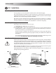
INSTALLATION 3.0 Installation 3.1 Pump Location and Installation Locate pump in an area convenient to solution tank and electrical supply. The pump should be accessible for routine maintenance, and should not be operated in ambient temperatures above 113°F (45°C). If the pump will be exposed to direct sunlight, LMI black, UV resistant tubing should be installed. This pump is cord connected and not intended for permanent mounting to a building.
INSTALLATION 3.2.2 Suction Lift - Wall Bracket Mount The pump may be mounted using an LMI Wall Mount Bracket Assembly (part no. 34643) directly above the solution tank. A pump mounted in this manner allows for easy changing of solution tanks or drums. 3.2.3 Suction Lift - Tank Mount The pump may be mounted on a molded tank provided there is a recess to keep the pump stationary. LMI 10-gallon tank (part no. 27421), 35-gallon tank (part no. 27400), and 50-gallon tank (part no.
INSTALLATION 3.3 Tubing Connections Use only LMI tubing. DO NOT USE CLEAR VINYL TUBING ON THE DISCHARGE SIDE OF THE PUMP. The pressure created by the pump can rupture vinyl tubing, which is only for connection to the return line of the FastPrime™ fitting. Before installation, all tubing must be cut with a clean square end. Valve and head connections from the factory are capped or plugged to retain pre-prime water. Remove and discard these caps or plugs before connecting tubing.
INSTALLATION 3.4 Four-Function Valves (4-FV) Your pump may be equipped with a 4-FV, or standard discharge valve. If your pump is not equipped with a four-function valve and you feel it is needed in your application, it can be purchased as an accessory. Contact your local LMI stocking distributor. The features of a 4-FV are listed below. 1. Pressure Relief: If the discharge line is over pressurized, the valve opens sending solution back to the supply tank. 2.
INSTALLATION 3.5 Four-Function Valve Installation Discharge 1/4" Through 1/4" Tubing Four-Function Valve Body Bleed Nut 4-FV Fitting To Solution Tank or Drum Coupling Nut To Pump Head To install a 4-FV, the 4-FV Fitting and Coupling Nut should be assembled with the appropriate cartridges into the discharge port of the pump. Use a 13/16” or 20 mm socket to tighten fitting. Tightening to 50 inch-pounds is recommended. Do not over tighten.
INSTALLATION 3.7 AutoPrime™ The AutoPrime™ Liquid End is equipped with a valve that allows for constant removal of vapors and gasses inherent with effervescent chemicals such as Sodium Hypochlorite and Hydrogen Peroxide. The valve keeps the pump primed automatically. When installing a pump equipped with an AutoPrime™ Liquid End connect the 1/2" OD Polyethylene tubing to the top vertical fitting, and route this line back to the supply tank.
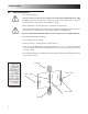
INSTALLATION 3.8 Foot Valve/Suction Tubing Installation The Foot Valve acts as a check valve to keep the pump primed in suction lift applications. The foot valve is designed to be submersed in the solution tank or drum and must sit in a vertical position at the bottom. Position approximately 2 inches (50 mm) off the bottom if the tank or drum contains sediment. Pump models equipped with high-viscosity liquid ends are not equipped with foot valves. Flooded suction is recommended.
INSTALLATION 3.9 Injection Check Valve and Discharge Tubing Installation The Injection Check Valve prevents backflow from a treated line. Install the injection check valve at the location where chemical is being injected into the system. Any size NPTF fitting or pipe tee with a reducing bushing to 1/2" NPTF will accept the injection check valve. Teflon® tape should only be used on threads that are connected with pipes.
Operation 4.0 Operation 4.1 Output Adjustment Controls 1. Power/Mode Selection Button: This button allows convenient starting and stopping of the pump. For pumps with external control capability (A3, A7, A8) this button switches pump operation between internal and external modes. When operating in internal mode the Pulse Indicator Light will flash green. When operating in external mode the Pulse Indicator Light will flash yellow. ➂ ➀ 2.
DETAIL D SCALE 5 : 1 OPERATION 7. External Control Connector (5-Pin): This connector is for the connection of various options and accessories that can be used to externally control the pump. The pin functions (and the wire color for the standard LMI external control cable) are as follows: ➁ ➂ ➄ ➃ DETAIL E SCALE 5 : 1 ➀ 1. Remote On Signal (Brown) 2. Ground/Return Connection (White) 3. External Pulse Signal (Blue) (used only with A3, and A7 Series pumps) 4. 18Volt Supply Voltage (Black) 5.
Operation 4.2.2 Start-Up/Priming for Pump Supplied with 4-FV Read this entire section completely before proceeding. When all precautionary steps have been taken, the pump is mounted, and the tubing is securely attached, you may now start priming the pump. If the pump does not self-prime, remove the 4-FV on the discharge side of the pump head. Remove the check valve and pour water or solution into the port until the head is filled. Replace valve, then follow start up/priming steps. 1.
Operation 4.3.1 Total Pump Output Calculate the approximate output of the pump as follows: When converting between different units, remember these conversion factors: 1 Gallon = 3.785 Liters 1 Day = 1,440 Minutes 240 SPM = 14,400 SPH PUMP OUTPUT = MAX PUMP OUTPUT x % SPEED x % STROKE Example: A151-928SI Use Max Output (from dataplate on side of pump) = 1 GPH (1 gallon per hour). If the pump is set at 60% speed and 70% stroke length, the approximate pump output is: 1.0 x 0.60 x 0.70 = 0.42 GPH.
Operation 4.3.3 Calibration in External Mode It may be helpful to decrease the speed of the pump in order to count the number of strokes. For accuracy count at least 120 strokes. 1. Since pump output is governed by an external device such as Flowmeter-Pulser, Liquitron™ Controller, or 4-20 mA DC signal from an instrument with an LMI Analog-to-Digital Converter, only the output per stroke may be calibrated. 2.
Operation 4.4 Methods of Externally Triggering or Pacing A3, A7, and A8 Pumps Method of Triggering A3, and A7 Pumps Through External Control Connector Pin 1. Switch Closure Switch closing triggers pump 2. NPN Transistor Base goes high to trigger pump 3. PNP Transistor Base goes low to trigger pump 4. Opto Isolator The default configuration for the Remote On/Off input is: open contacts = pump stopped, closed contacts = pump enabled.
OPERATION 4.4.1 Control Modes 4.4.1.1 Local Mode • When in Local mode the A3 pump runs continuously at maximum speed. • When in Local mode A7 and A8 pumps run at the speed indicated by the speed knob. 4.4.1.2 Remote Mode (for A3, and A7) The default definition of a pulse is: close = pulse starts, open = pulse ends. Pins 1 (brown wire) and 2 (white wire) must be connected/shorted together in order for the pump to respond to pulses in external mode.
Operation 4.4.1.4 Calibrating the Analog Input Settings (for A8) 1. Press and hold the Power/Mode Selection Button for more than 5 seconds. This enters the calibration mode. Pumping will stop while in calibration mode. 2. Turn the Speed Adjustment Knob completely clockwise P to enter the fast level analog input state. The Pulse Indicator Light will flash 1 second green ¼ second yellow. 3. Apply the desired fast level analog signal and press the Power/Mode Selection Button for less than 3 seconds.
Maintenance 5.0 Spare Parts Replacement and Routine Maintenance LMI recommends replacing the elastomeric components of the pump on an annual basis. Refer to the LMI Metering Pump Price List for the proper Spare Parts Kit or RPM Pro Pac™ kit number or contact your local LMI stocking distributor. 5.1 Depressurizing the Discharge Line (for Pumps Equipped with a 4-FV Only) ALWAYS wear protective clothing, face shield, safety glasses and gloves when performing any maintenance or replacement on your pump.
MAINTENANCE 5.3 Liquifram™ (Diaphragm) Replacement ALWAYS wear protective clothing, face shield, safety glasses and gloves when working near or performing any maintenance or replacement on your pump. See MSDS information from solution supplier for additional precautions. LMI metering pumps are designed for trouble-free operation, yet routine maintenance of elastomeric parts is essential for optimum performance.
Maintenance 5.4 Cartridge Valve and O-ring Replacement ALWAYS wear protective clothing, face shield, safety glasses and gloves when working on or performing any maintenance or replacement on your pump. See MSDS information from solution supplier for additional precautions. Refer to the LMI Metering Pump Price List for the proper Spare Parts Kit or RPM Pro Pac™ kit number or contact your local LMI stocking distributor. 1. Carefully depressurize and disconnect the discharge line (see Section 5.1 or 5.
Maintenance 5.5 Injection Check Valve Parts Replacement Depressurize and drain pipeline (or isolate Injection Check Valve point using valves) so that Injection Check Valve can safely be disassembled. ALWAYS wear protective clothing, face shield, safety glasses and gloves when working near or performing any maintenance or replacement on your pump. See MSDS information from solution supplier for additional precautions.
Maintenance 5.6 FastPrime™ Valve O-Ring Replacement ALWAYS wear protective clothing, face shield, safety glasses and gloves when performing any maintenance or replacement on your pump. Refer to the LMI Metering Pump Price List for the proper Spare Parts Kit or RPM Pro Pac™ kit number or contact your local LMI stocking distributor. 1. Be sure the Injection Check Valve is properly installed and is operating. If a shut off valve has been installed downstream of the Injection Valve, it should be closed.
Maintenance 5.6 FastPrime™ Valve O-Ring Replacement (continued) 6. Recut 1 to 2 inches off the tip of the return line and ensure the end is squared. Press the return line tubing on completely past the barbs.
Maintenance 5.7 Stroke Length Setting The Stroke Adjustment Knob is calibrated for each pump, and does not need to be removed during Liquifram™ replacement or during most other maintenance. If the Stroke Knob is removed for any reason it becomes necessary to reset the stroke length. Follow the procedure below to approximate the proper factory setting. If a more accurate setting is required contact your distributor or manufacturer. 1. Install a new Stroke Shaft.
Maintenance 320 5.
Maintenance 5.9 EPU Wiring Diagram A0/A1 PULSER A3/A7/A8 PULSER P2 P4 P1 P3 P4 P1 P3 P2 BLK OR BRN YEL WHT OR BLU WHT OR BLU BLK OR BRN GRN OR GRN/YEL GRN OR GRN/YEL YEL YEL YEL EPU ASSEMBLY POWER CORD EPU ASSEMBLY POWER CORD 5.
Maintenance 613 40 615 40 616 A. B. C. D. 601 603 601 90 604 90 604 100 90 10 100 190 140 606 150 100 100 603 90 603 602 602 90 603 90 A. B. C. 605 D.
Maintenance 613 40 615 40 616 C. A. D. B. 601 603 90 601 604 90 604 100 90 10 100 606 190 140 150 180 100 100 603 605 90 603 602 602 90 603 90 C. A. D. B.
Maintenance 614 40 616 603 611 612 100 190 10 40 100 610 616 100 606 603 609 613 603 602 616 40 613 AutoPrimeTM Liquid End 35
Maintenance 618 100 606 120 10 90 190 619 SS Liquid End 36
Troubleshooting 6.0 Troubleshooting PROBLEM Pump Will Not Prime Pump Loses Prime POSSIBLE CAUSE 1. Pump not turned on or plugged in. 2. Output dials not set properly. SOLUTION 1. Turn on pump/plug in pump. 2. Always prime pump with speed and stroke at 100%. 3. Foot Valve not in vertical position on 3. Foot Valve must be vertical (see Foot bottom of tank. Valve Installation, Section 3.7). 4. Pump suction lift too high. 4. Maximum suction lift is 5 ft (1.5 m).
troubleshooting 6.0 Troubleshooting (continued) PROBLEM Leakage at tubing POSSIBLE CAUSE 1. Worn tubing ends. 2. Loose or cracked fitting. 3. Worn seal rings. Low Output or Failure to Pump Against Pressure 4. Solution attacking Liquid Handling Assembly 1. Pump’s maximum pressure rating is exceeded by injection pressure. 2. Worn Seal Rings. 3. Ruptured Liquifram™. 4. Incorrect stroke length. 5. Tubing run on discharge may be too long. 6. Clogged Foot Valve strainer. Failure to Run 1.
NOTES 39
201 Ivyland Rd. Ivyland, PA 18974 TEL: (215) 293-0401 FAX: (215) 293-0445 http://www.lmipumps.com © 2009 LMI Milton Roy - All Rights Reserved Printed in USA Specifications subject to change without notice. Liquifram, Liquitron, Micropace, FastPrime, AutoPrime, and Pro Pac are trademarks of Milton Roy Company, Roytronic is a registered trademark of Milton Roy Company, Teflon is a registered trademark of E. I. du Pont de Nemours & Co., Inc.