
User Manual

35
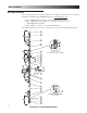
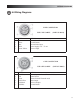
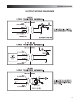
WIRING DIAGRAMS
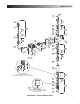
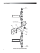
6.0 Wiring Diagrams
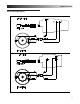
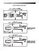
5 PIN CONNECTOR
USE 5 PIN CABLE (LMI P/N 48414)
PIN WIRE SIGNAL
1
2
3
4
5
White
Green-Yellow
Remote On-Off
Ground-Return
External Pulse Input
4-20 mA Input
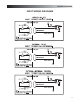
6 PIN CONNECTOR
USE 6 PIN CABLE (LMI P/N 49035)
PIN WIRE SIGNAL
1
2
3
4
5
6
Red-White
Red
Green
Red-Yellow
Alarm Output or Internal-External indicator
Alarm Return
Remote Internal-External mode
Pulse Output
4-20 mA Output
Ground-Return