
User Manual

17
OPERATION
4. Pulse Out (AD9) (Red/Yellow) – On the AD9 this pin gives a100ms
pulse output for each pump stroke.
5. 4-20mA Out (AD9) (Red/Black) – On the AD9 this pin is the positive
4-20ma output. This output will show you 4ma when the pump is idle,
20ma at max stroke speed.
6. Ground/Return Connection (Red/Blue)– Common Ground
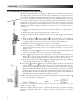
10. External Control Connector (5-Pin): This connector is for the connec-
tion of various options and accessories that can be used to externality
control the pump. The pin functions (and the wire color for the standard
LMI external control cable) are as follows:
1. Remote On/Off Signal (Brown)
2. Ground/Return Connection (White)
3. External Pulse Signal (Blue)
4. 24V 75 mA* Power Supply (Black)
5. 4-20mA Input Signal (Green/Yellow)
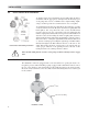
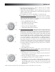
11. Low-Level Connector (3-Pin): This connector is for the connection of
a Low-Level Sensor (49246) or a Dual-Level Sensor (49249). The Tank
Empty input connections are always active for all models in all func-
tional modes. The Tank Low input connections are always active for
models equipped with dual level functionality (AD8, AD9). If the uid
level drops below the top oat on a Dual-Level Sensor, the Low-Level
Indicator Light will turn yellow. If the uid level drops below the oat
on a Low-Level Sensor, or the bottom oat on a Dual-Level Sensor,
the Low-Level Indicator Light will turn red, and the pump will stop.
The pump is designed to recognize an open circuit as full and a closed
circuit as low or empty. There is a ve second delay between triggering
the sensor, and the pump’s reaction. This is intended to avoid trigger-
ing during relling your supply tank. The pin functions are as follows:
1. Tank Empty Signal
3. Tank Low Signal
4. Ground/Return Connection
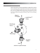
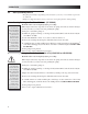
12. Flow Monitor/Meter Connector (4-Pin): This connector will be used
with a Milton Roy ow meter or the Milton Roy Digpulse ow monitor
(FM-ROY-9). The pin functions are as follows:
1. Flow Meter In – A closure between this pin and ground registers a
pulse for the ow meter/monitor.
2. 24 Volt 75 mA* Supply – Supply voltage for a Milton Roy ow meter.
3. Ground/Return Connection – Common ground
4. Flow Meter Sense – The condition of this pin will set the pump into
the Digipulse or Flow Meter mode. This will automatically occur
with the Milton Roy device is connected. A connection to ground
indicates the use of a ow meter, while an open circuit indicates a
ow monitor.
*The total current output of the 5-pin and 4-pin connectors should not exceed 75 mA.