
User Manual

16
OPERATION
4.0 Operation
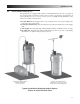
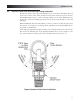
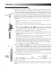
4.1 Output Adjustment Controls
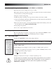
1. Power Button: This button allows convenient starting and stopping of
the pump.
2.
Mode Selection Button: For pumps with external control capability (AD8,
AD9) this button switches pump operation between internal and external
modes. When operating in internal mode the Pulse Indicator Light will ash
green while pumping. When operating in external mode the Pulse Indicator
Light will ash yellow while pumping.
3.
Down Button: This button reduces the stroke speed of the pump. It will
reduce the stroke speed by 1 each time it is pressed. If this button is held
down, it will rapidly reduce the stroke speed. When a speed of 1 stroke per
minute (SPM) is reached the speed can be further reduced by pressing this
button again to enter stroke per hour settings.
4.
Up Button: This button increases the stroke speed of the pump. It will
increase the stroke speed by 1 each time it is pressed. If this button is held
down, it will rapidly increase the stroke speed. When a speed of 59 strokes
per hour (SPH) is reached the speed can be further increased by pressing this
button again to enter stroke per minute settings.
5. LCD Display: This display will show the stroke speed of the pump. Pumps
with theoretical (AD2, AD8, AD9) or actual (AD9 when combined with a
ow meter) ow will display the ow here.
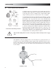
6. Stroke Adjustment Knob: This knob provides adjustment of the stroke length.
Turning this knob clockwise 3 increases the stroke length, which results in
a higher amount of chemical displaced per stroke. It is recommended that
the stroke range stay between 20% and 100%.
7. Pulse Indicator Light: This light will ash green when pumping in internal
mode and will ash yellow when pumping in external mode. The light is on
between strokes and off during the actual stroke.
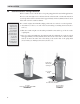
8. Low-Level Indicator Light: For units with Single-Level Float Sensors this
light will turn red when the Low-Level Sensor registers empty. This will turn
the pump off. For units compatible with Dual-Level Sensors (AD8, AD9) the
light will turn yellow when a low level is registered, and red when an empty
level is registered. The pump will turn off when it registers an empty level.
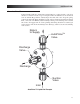
9. Output, Alarm, & Remote Mode Connector (6-Pin): This connector is used
for the special functions associated with the AD9 controls. For the AD9
this connector is associated with the 4-20ma out, Alarm Out, and Internal/
External remote modes.
1. Alarm Out (Red/White) – Programmed as either an Alarm Output or
Internal/External mode indicator. As an Alarm Output, pins 1 and 2 will
give a closure (solid state) triggered by: empty tank indication, input pulse
error, exceed batch error, or ow switch activation. For remote mode
indication it is open for internal mode and closed for external.
2. Alarm Return (Red) – Return side for the above pin 1 Alarm Out.
3. Remote Internal/External Mode (AD9) (Green) – This pin is programmed
as Internal/External remote mode control for an AD9. If programmed as
the Internal/External control, a closure will put the AD9 into external
mode.