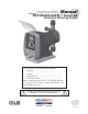
Instruction Manual ROYTRONIC EXCEL™ Series AD Electronic Metering Pumps For file reference, please record the following data: Model No: _____________________________________ Serial No: _____________________________________ Installation Date: ________________________________ Installation Location: _____________________________ When ordering replacement parts for your LMI Metering Pump or Accessory, please include complete Model Number and Serial Number of your unit.
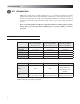
ROYTRONIC EXCEL™ Series AD Model AD 2 5 1 - 8 3 8 S I Model Code Configuration *VU[YVS *VKL AD2 - Dual Manual Control – Digital: Stroke frequency and length manually adjustable with digital LCD display, low level indication (remote input). Display configurable to indicate calculated pump flow.
Contents 1.0 2.0 3.0 4.0 5.0 6.0 7.0 Precautions . . . . . . . . . . . . . . . . . . . . . . . . . . . . . . . . . . . . . . . . . . . . . . . . . . . . . . . . . . . . . . . . 4 Introduction . . . . . . . . . . . . . . . . . . . . . . . . . . . . . . . . . . . . . . . . . . . . . . . . . . . . . . . . . . . . . . . . . 6 2.1 Specifications . . . . . . . . . . . . . . . . . . . . . . . . . . . . . . . . . . . . . . . . . . . . . . . . . . . . . . . 6 2.2 Unpacking Check List . . . . . . . . . . . . . .
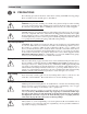
PRECAUTIONS 1.0 PRECAUTIONS The following precautions should be taken when working with LMI metering pumps. Please read this section carefully prior to installation. Protective Clothing ALWAYS wear protective clothing, face shield, safety glasses and gloves when working on or near your metering pump. Additional precautions should be taken depending on the solution being pumped. Refer to MSDS precautions from your solution supplier.
PRECAUTIONS Back Pressure/Anti-Syphon Valve If you are pumping downhill or into low or no system pressure, a back pressure/antisyphon device such as LMI’s Four-Function Valve should be installed to prevent overpumping or syphoning. Contact your LMI distributor for furthur information. Electrical Connections WARNING: To reduce the risk of electrical shock, the metering pump must be plugged into a properly grounded grounding-type receptacle with ratings conforming to the data on the pump control panel.
INTRODUCTION 2.0 Introduction LMI is the world’s most versatile manufacturer of economical and efficient metering pumps. This manual addresses the installation, maintenance and troubleshooting procedures for manually and externally controlled pumps. LMI has a worldwide network of stocking representatives and authorized repair centers to give you prompt and efficient service. Please review this manual carefully. Pay particular attention to warnings and precautions.
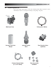
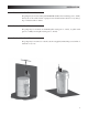
UNPACKING CHECK LIST 2.2 Unpacking Check List Your carton will contain many or all of the following items. Please notify the carrier immediately if there are any signs of damage to the pump or its parts.
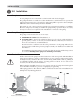
INSTALLATION 3.0 Installation 3.1 Pump Location and Installation Locate pump in an area convenient to solution tank and electrical supply. The pump should be accessible for routine maintenance, and should not be operated in ambient temperatures above 113°F (45°C). If the pump will be exposed to direct sunlight, LMI black, UV resistant tubing should be installed. This pump is cord connected and not intended for permanent mounting to a building.
INSTALLATION 3.2.2 Suction Lift - Wall Bracket Mount The pump may be mounted using an LMI Wall Mount Bracket Assembly (part no. 34643) directly above the solution tank. A pump mounted in this manner allows for easy changing of solution tanks or drums. 3.2.3 Suction Lift - Tank Mount The pump may be mounted on a LMI 10-gallon tank (part no. 27421), 35-gallon tank (part no. 27400), and 50-gallon tank (part no. 26350). 3.2.
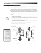
INSTALLATION 3.3 Tubing Connections the larger opening of the Coupling Nut toward the tubing end. 2a. For 1/4” OD tubing: Position the Female Ferrule so that 1/4” to 3/8” (5-10 mm) of tubing protrudes from the Female Ferrule. Orient the raised collar of the Ferrule toward the Coupling Nut (reference FIGURE 1). 2b.
INSTALLATION 3.4 Four-Function Valves (4-FV) Your pump may be equipped with a 4-FV, or standard discharge valve. If your pump is not equipped with a four-function valve and you feel it is needed in your application, it can be purchased as an accessory. Contact your local LMI stocking distributor. The features of a 4-FV are listed below. 1. Pressure Relief: If the discharge line is over pressurized, the valve opens sending solution back to the supply tank. 2.
INSTALLATION 3.5 Four-Function Valve Installation To install a 4-FV, the 4-FV Fitting and Coupling Nut should be assembled with the appropriate cartridges into the discharge port of the pump. Use a 13/16” or 20 mm socket to tighten fitting. Tightening to 50 inch-pounds is recommended. Do not over tighten. Four-Function Valve Tubing Connection To assemble the Four-Function Valve Body, insert the large opening on the Four-Function Valve Body into the 4-FV Coupling Nut and hand tighten.
INSTALLATION 3.7 AutoPrime™ Pumps installed with the AutoPrime™ Liquid End are equipped with a valve that allows for constant removal of vapors and gasses inherent with effervescent chemicals such as Sodium Hypochlorite and Hydrogen Peroxide. The valve keeps the pump primed automatically. When installing a pump equipped with an AutoPrime™ Liquid End, connect the 1/2" OD Polyethylene tubing to the top vertical fitting, and route this line back to the supply tank.
INSTALLATION 3.8 Foot Valve/Suction Tubing Installation The Foot Valve acts as a check valve to keep the pump primed in suction lift applications. The foot valve is designed to be submersed in the solution tank or drum and must sit in a vertical position at the bottom. Position approximately 2 inches (50 mm) off the bottom if the tank or drum contains sediment. Pump models equipped with high-viscosity liquid ends are not equipped with foot valves. Flooded suction is recommended.
INSTALLATION 3.9 Injection Check Valve and Discharge Tubing Installation The Injection Check Valve prevents backflow from a treated line. Install the injection check valve at the location where chemical is being injected into the system. Any size female NPT fitting or pipe tee with a reducing bushing to 1/2" female NPT will accept the injection check valve. PTFE tape should only be used on threads that are connected with pipes.
OPERATION 4.0 Operation 4.1 Output Adjustment Controls Power Button: This button allows convenient starting and stopping of the pump. 2. Mode Selection Button: For pumps with external control capability (AD8, AD9) this button switches pump operation between internal and external modes. When operating in internal mode the Pulse Indicator Light will flash green while pumping. When operating in external mode the Pulse Indicator Light will flash yellow while pumping. 1. 3.
OPERATION 4. Pulse Out (AD9) (Red/Yellow) – On the AD9 this pin gives a100ms pulse output for each pump stroke. 5. 4-20mA Out (AD9) (Red/Black) – On the AD9 this pin is the positive 4-20ma output. This output will show you 4ma when the pump is idle, 20ma at max stroke speed. 6. Ground/Return Connection (Red/Blue)– Common Ground 10. External Control Connector (5-Pin): This connector is for the connection of various options and accessories that can be used to externality control the pump.
OPERATION 4.2 Start-up and Adjustment r 5IF QVNQ JT OPSNBMMZ TFMG QSJNJOH JG TVDUJPO MJGU JT GU N PS MFTT BOE UIF TUFQT CFMPX BSF GPMMPXFE r 1VNQT BSF TIJQQFE GSPN UIF GBDUPSZ XJUI XBUFS JO UIF QVNQ IFBE UP BJE JO QSJNJOH 4.2.1 Start-Up/Priming for FastPrime™ Heads (LE-XXXNX) Read this entire section completely before proceeding. If the pump does not self-prime, remove the fitting on the discharge side of the pump head.
OPERATION 4.2.3 Start-Up/Priming for AutoPrime™ Heads (LE-XXXAX or LE-XXXHX) Read this entire section completely before proceeding. When all precautionary steps have been taken, the pump is mounted, and the tubing is securely attached, you may prime the pump. 1. Plug in or switch on the pump. 2. While the pump is running, set the speed knob and the stroke knob at 100%. 3. The suction tubing should begin to fill with solution from the tank as the AutoPrime™ valve purges air from the pump head. 4.
OPERATION 4.3.2 Calibrating the Displayed Flow (AD2, AD8) The Roytronic Excel Pumps are equipped to display a theoretical flow rate based upon the pump’s stroke speed and stroke length. These calculations are based upon factory test conditions which may be significantly different from your application. It is necessary for the user to perform the following calibration procedure when the pump is connected to your system, and using the actual chemical.
OPERATION 4.4 Methods of Externally Triggering or Pacing AD8 and AD9 Pumps Method of Triggering AD8 and AD9 Pumps through External Control Connector PIN 1. Switch Closure Switch closing triggers pump 2. NPN Transistor Base goes high to trigger pump 3. PNP Transistor Base goes low to trigger pump 4. Opto Isolator Blue 3 White 2 + Blue 3 − White 2 + Blue 3 − White 2 + Blue 3 − White 2 Switch or transistors must be capable of switching 24V DC at 15 milliamperes.
OPERATION 4.4.1 Control Modes 4.4.1.1 Local/Internal Mode r 8IFO JO -PDBM NPEF 3PZUSPOJD &YDFM QVNQT SVO BU UIF TQFFE JOEJDBUFE PO UIF -$% Display. r 5IF TUSPLJOH TQFFE DBO CF BEKVTUFE GSPN UIF NBYJNVN TQFFE PG TUSPLFT QFS NJOVUF 41. down to 1 stroke per hour (SPH). 4.4.1.2 Changing Displayed Flow Units (AD2, AD8) 1. When in Internal Mode use the Power Button to turn the pump off. 2.
MAINTENANCE 5.0 Spare Parts Replacement and Routine Maintenance LMI metering pumps are designed for trouble-free operation, yet routine maintenance of elastomeric parts is essential for optimum performance. This involves replacing the Liquifram™, cartridge valves, O-rings, and the injection check valve spring. LMI recommends replacing these parts at least once a year; however, frequency will depend on your particular application. 5.
MAINTENANCE 5.3 Liquifram™ (Diaphragm) Replacement ALWAYS wear protective clothing, face shield, safety glasses and gloves when working near or performing any maintenance or replacement on your pump. See MSDS information from solution supplier for additional precautions. LMI metering pumps are designed for trouble-free operation, yet routine maintenance of elastomeric parts is essential for optimum performance.
MAINTENANCE 5.4 Cartridge Valve and O-ring Replacement ALWAYS wear protective clothing, face shield, safety glasses and gloves when working on or performing any maintenance or replacement on your pump. See MSDS information from solution supplier for additional precautions. Refer to the LMI Metering Pump Price List for the proper Spare Parts Kit or RPM Pro Pac™ kit number or contact your local LMI stocking distributor. 1. Carefully depressurize and disconnect the discharge line (see Section 5.1 or 5.
MAINTENANCE 5.5 Injection Check Valve Parts Replacement Depressurize and drain pipeline (or isolate Injection Check Valve point using valves) so that Injection Check Valve can safely be disassembled. ALWAYS wear protective clothing, face shield, safety glasses and gloves when working near or performing any maintenance or replacement on your pump. See MSDS information from solution supplier for additional precautions.
MAINTENANCE 5.6 FastPrime™ Valve O-Ring Replacement ALWAYS wear protective clothing, face shield, safety glasses and gloves when performing any maintenance or replacement on your pump. Refer to the LMI Metering Pump Price List for the proper Spare Parts Kit or RPM Pro Pac™ kit number or contact your local LMI stocking distributor. 1. Be sure the Injection Check Valve is properly installed and is operating. If a shut off valve has been installed downstream of the Injection Valve, it should be closed.
MAINTENANCE 5.6 FastPrime™ Valve O-Ring Replacement (continued) 6. Recut 1 to 2 inches off the tip of the return line and ensure the end is squared. Press the return line tubing on completely past the barbs.
MAINTENANCE 5.
MAINTENANCE 30 Bubble Number Description Bubble Number Description 75 EPU O-Ring 230 Control Panel O-Ring 80 EPU Return Spring 240 Wire Harness 90 EPU Shim 250 Drive Assembly Screws 125 Plunger O-Ring 260 Female Stroke Shaft 130 Retaining Ring 265 Male Stroke Shaft 132 Stroke Bracket 270 Stroke Shaft O-Ring 134 Stroke Bracket Screw 285 PCB Attachment Screw 136 Stroke Bracket Washer 310 Shaft Seal 140 Drive Housing 320 Adapter Disk 150 EPU Attachment Bolt 340 Clea
MAINTENANCE 5.
MAINTENANCE 5.9 Liquid End Parts For the latest and most accurate information on your liquid end, please refer to the Liquid End Sheets available in the LMI Online Library at: www.lmipumps.com. 1. Select “Online Literature Library” in the Navigation Bar on left. 2. Once on Online Literature Library use “Product” drop down to select “Liquid Handling Assemblies.” 3. Select “Gallery” or ”Index” to view Liquid End sheets. The following images are for reference and may not represent your particular liquid end.
MAINTENANCE '(3(1',1* 21 78%,1* 6,=( 7+( )(558/( *(20(75< :,// %( ',))(5(17 '(3(1',1* 21 &$575,'*( '(6,*1 $1 2 5,1* 0$< %( 35(6(17 $6 3$57 2) 7+( $66(0%/< AutoPrime™ Liquid End Assembly 33
MAINTENANCE 237,21$/ 3,3( $1' 3,3( ),77,1*6 $5( &86720(5 6833/,(' '2 127 $33/< 37)( 7$3( 72 7+,6 7+5($' 3,3( $1' 3,3( ),77,1*6 $5( &86720(5 6833/,(' 237,21$/ Stainless Steel Liquid End Assembly 34
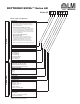
WIRING DIAGRAMS 6.
WIRING DIAGRAMS INPUT WIRING DIAGRAMS 36
WIRING DIAGRAMS INPUT WIRING DIAGRAMS 37
WIRING DIAGRAMS INPUT WIRING DIAGRAM 4 38
WIRING DIAGRAMS OUTPUT WIRING DIAGRAMS 39
TROUBLESHOOTING 7.0 Troubleshooting PROBLEM Pump Will Not Prime POSSIBLE CAUSE 1. Pump not turned on or plugged in. 2. Output dials not set properly. 3. Foot Valve not in vertical position on bottom of tank. 4. Pump suction lift too high. 5. Suction tubing is curved or coiled in tank. 6. Fittings are over tightened. 7. Air trap in suction valve tubing. 8. Too much pressure at discharge. (Pumps without multi-function valve.) 9. Air leak around fitting. Pump Loses Prime 1. Solution container ran dry.
TROUBLESHOOTING PROBLEM Leakage at tubing POSSIBLE CAUSE 1. Worn tubing ends. 2. Loose or cracked fitting. 3. Worn seal rings. 4. Solution attacking Liquid Handling Assembly Low Output or Failure to 1. Pump’s maximum pressure rating is Pump Against Pressure exceeded by injection pressure. 2. Worn Seal Rings. 3. Ruptured Liquifram™. 4. Incorrect stroke length. 5. Tubing run on discharge may be too long. 6. Clogged Foot Valve strainer. Failure to Run 1. Pump not turned on or plugged in. 2. EPU failure.
— NOTES —
— NOTES —
sales@novatech-usa.com www.novatech-usa.com Tel: (866) 433-6682 Fax: (866) 433-6684 Tel: (281) 359-8538 Fax: (281) 359-0084 © 2011 LMI Milton Roy - All Rights Reserved Specifications subject to change without notice. 201 Ivyland Rd. Ivyland, PA 18974 TEL: (215) 293-0401 FAX: (215) 293-0445 http://www.lmipumps.com Liquifram, Liquitron, Micropace, FastPrime, AutoPrime, and Pro Pac are trademarks of Milton Roy Company, Teflon is a registered trademark of E. I. du Pont de Nemours & Co., Inc.