Adam Equipment GK INDICATOR (P.N. 9264, Revision K1, July 2011) V1.17 GK-H scales for Europe V2.25 EC Approved scale V3.32 GK scale for Europe V4.07 GK-H scale for USA V5.
Easy Reference: Model name of the indicator: Serial number of the unit: Software revision number (Displayed when power is first turned on): Date of Purchase: Name of the supplier and place: © Adam Equipment Company 2011
CONTENTS 1. INTRODUCTION ..................................................................................... 3 2. SPECIFICATIONS .................................................................................. 5 3. INSTALLATION ...................................................................................... 7 3.1. UNPACKING..................................................................................... 7 4. LOCATING..............................................................................
16.2. USING “2006” TO ENTER THE SERVICE PARAMETERS ........ 50 16.2.1 F1 -CALIBRATION ................................................................. 52 16.2.2 F2–DECIMAL POINT POSITION............................................ 53 16.2.3 F3 – CAPACITY ..................................................................... 53 16.2.4 F4 –INITIAL ZERO RANGE.................................................... 54 16.2.5 F5 -RE-ZERO RANGE ........................................................... 54 16.2.
1. INTRODUCTION • The GK indicator provides an accurate, fast and versatile general purpose indicator with parts counting, percent weighing and checkweighing functions. • The GK has LEDs to indicate when a weight is below the low limit, between the limits or above the high limit next to the display. These can work in conjunction with an audible alarm for check weighing as well as LCD showing LO, OK and HI. • The GK is supplied with a RS-232 bi-directional interface and real time clock (RTC).
4 © Adam Equipment Company 2011
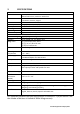
2. SPECIFICATIONS Load Cells Connection Excitation Sensitivity Linearity Zero Range Signal range ADC Sensitivity DIGITAL SECTION Maximum Range Divisions Weigh units Stabilisation Time Operating Temperature Power supply Battery INPUT SECTION Up to 4 , 350 ohm load cells Minimum 87 ohms, maximum 1120 ohms 6 wires 2 excitation, 2 sense, 2 signal 5Vdc 0.15uv/d (GK-M, 1.5uv/e) 0.01% FS 0- 10mv 0-40mv Approximately 0.
6 © Adam Equipment Company 2011
3. INSTALLATION 3.1. UNPACKING This indicator must be connected to a load cell platform and calibrated as necessary to match the platform and user requirements. See Section 15 for set-up information. The users application and the technical specifications of the platform or load cell will determine the necessary configuration. 4. LOCATING • The scales should not be placed in a location that will reduce the accuracy. • Avoid extremes of temperature.
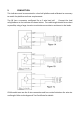
5. CONNECTION This indicator must be connected to a load cell platform and calibrated as necessary to match the platform and user requirements. The GK has a connector configured for a 6 wire load cell. Connect the load cells/platform to the indicator as shown below. The cable length should be as short as possible, using a large size wire to minimise errors due to resistance in the leads. GK-M model must use the 6 wire connection and has certain limitations for wire size and length.
Figure 1A shows the connections to a 6 wire load cell. Figure 1B shows a preferred method to attach a 4 wire load cell, using a 6 conductor cable to go from the indicator to the platform or load cell where it connects to the 4 wires from the load cells. The Excitation and sense wires are connected together near the load cell. For less exacting applications you can connect the excitation to the sense at the connector.
[Low Limit] & It sets the limits for check weighing and None allows setting of either the low limit or the high limit or both. [High Limit] [ Lim] It stores and recalls any of 10 preset limits None [Func] This is used to select percent weighing, RS- None 232 parameters, Operation of the bar graph, RTC settings, User ID and Scale ID. [Count] Enter Parts Counting [Print] It is used to print the results to a PC or None printer using the RS-232 interface.
6. DISPLAY 6.1.
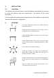
Next to the LCD are a number of LED’s that show when the weight is below, within or over the limits during check weighing. Weight LED LCD below the low limit Amber LO Within the limits Green OK Red HI Above the high limit NOTE: The LED’s can be set by the user to off, bar, spot or segment mode. See “F3 LED” in section 13.
The Counters are incremented any time the calibration section or the Factory parameters section have been modified. At power on, the display will show the current software revision number followed by the message of the Calibration Count “[AL[nt” then a number i.e. “123”. The number from the counter memory. Then the Parameter Counter message of “PAr[nt” and probably a different number, i.e. “234”. The counters cannot be reset to 0, they will increment until the display can no longer hold the values.
8. BATTERY • The indicators can be operated from the rechargeable battery, if desired. The battery life is determined by the number and impendence of the load cells connected. With a single load cell and backlight disabled the life is approximately 70 hours before needing to be recharged. • When the battery needs charging a symbol on the display will turn on. The battery should be charged when the symbol is on.
11. OPERATION 11.1. ZEROING • You can press the [Zero] key at any time to set the zero point from which all other weighing and counting is measured. This will usually be necessary when the platform is empty. When the zero point is obtained the display will show the zero indicator. • The indicator has an automatic re-zeroing function to account for minor drifting or accumulation of material on a connected platform.
NOTE: When the container is removed a negative value will be shown. If the indicator was tared just before removing the container, this value is the gross weight of the container plus all products which were removed. The zero indicator will also be on as the platform is back to the same condition it was when [Zero] was pressed last. If the value to be tared is very large the scale may not allow you to tare the value as the negative value will not fit on the display area.
11.3. WEIGHING To determine the weight of a sample, first tare an empty container if used, then place the sample in the container. The display will show the weight and the unit of weight currently in use. To change the weighing unit press the [Unit] key. The only alternative weighing unit is pounds. This can be enabled by the user in the parameters section. See section 13.3. 11.4. PARTS COUNTING The indicator can be used to count parts based on the average weight of a sample weighed.
• Either place 10 parts on the platform for determining the average piece weight or use a different number of parts. For example, place 20 parts on the platform, press [CE] to clear the last values and then enter the value 20 using the numeric keypad. • Press [Cnt] to weigh the samples and determine an average piece weight. • If the parts are too light to measure accurately, the count may become faulty.
• To count a different sample quantity, press the [Count] key. The display will show the last used sample size. Either use this sample size with a different part or enter a new sample size as above. • To return to weighing, press [Unit] when “XX pcs” is displayed.
11.5. CHECK-WEIGHING Check-weighing is a procedure to display an indicator or sound an alarm when the weight on the platform meets or exceeds the values stored in the memory. The memory holds values for a high limit and a low limit. Either or both the limits can be set by the user. NOTE: 1. The alarm and the LED bargraph can each be set to OFF (See section 13.1). The LCD display will indicate whenever the weight is within or exceeds the limits by showing ‘OK’, ‘HI’ or ‘LO’.
11.5.1 SETTING UP WHILE WEIGHING • Press the [Low Limit] key. It will show the current low limit. The “LO” symbol will appear on the display. • Press the [CE] key to clear the old value and then enter the new low limit using the numeric keys. The decimal point is fixed at the position that is used for the current weighing unit. When the desired value is shown press [Tare] to accept the value. If you want to reset the value to zero, press [CE] to clear the value.
11.5.2 SETTING UP WHILE PARTS COUNTING OR % WEIGHING During parts counting and percent weighing the limits are set in the same way as above. The limits are displayed in pcs or %. See Section 10.4 for the description of parts counting and Section 10.7 for percent weighing. NOTE: 11.6. 1. The weight must be greater than 20 scale divisions for the checkweighing to operate. 2. To disable the check weighing function, enter zero into both the limits as described above.
Press the [ Lim] key. If you are already in the check weighing mode the display will ask if you wish to store the current limits by showing “StOrE” or recall another set of limits by showing “rECALL”. The [ Lim] key can be used to toggle between “StOrE” and “rECALL”. If you want to store the limits, when “StOrE” is displayed press the [Tare] key. The display shows “St ”. Enter a number corresponding to the desired memory location (0 to 9).
NOTE: 1. If the recalled limit is for parts counting, the display will show the last sample value used, ready for a new sample to be counted. 2. If the recalled unit is a percent weighing limit, the display will show the last sample value used, ready for a new sample to be weighed. 3. If the memory location was empty the indicator will return to weighing. 11.7. PERCENT WEIGHING The indicator can be set to perform percent weighing. See Section 13.1.
• Press [Tare] again to enter percent weighing. The indicator will set the sample mass on the platform as 100% reference weight. NOTE: If there is no reference weight on the pan and percent weighing function is entered, pressing [Tare] again will return the indicator to normal weighing. • Remove the sample weight. Then any other weight placed on the platform will be displayed as a percentage of the original sample.
• If the indicator shows “x x . x x %”, which is the last weight used as a reference, press [CE] to clear and use the numeric keypad to enter a new value. Press [Tare] to accept the new reference weight. • The weight entered must be greater than 50 scale divisions. • Press [Unit] to return to normal weighing. NOTE: The display may jump by large numbers unexpectedly if small weights are used to set as 100% reference. The indicator checks if the weight is too small and will show Error 7.
11.8. ANIMAL (DYNAMIC) WEIGHING The indicator can be set to animal (dynamic) weighing for weighing any items that are unstable or may move. See Section 13.4. The indicator uses a special filter to minimise the effects of any movement on the platform. • Press [Func]. The first option is “FUnC 1”, press the [Func] key 3 more times to display “Func 4”. • Press the [Tare] key. “F4 PCt” will be displayed. Press the [Func] key to advance to the second function, “F4 AnL”, Animal weighing.
11.8.1 ANIMAL WEIGHING PROCEDURE • With the platform empty the display will show zero weight.. Place containers or blankets onto the platform and press the [Tare] key to zero the display. The indicator may go into the animal weighing procedure when the items are placed on the platform but will return to showing zero when the [Tare] key is • Place the animal to be weighed on the platform.
11.9. ACCUMULATED TOTAL The indicator can be set to accumulate when a weight is added to the platform automatically or manually by pressing [Print]. See Section 13.2. NOTE: 1. The accumulation function is available only during weighing. It is disabled during parts counting or percent weighing. 2. The accumulated weights will be stored in either kg or lb, depending upon the weighing unit in use. 3. If at any time the weighing units are changed, the accumulated data will be lost. 11.9.
• When the indicator is at zero place a second weight on the platform. When stable press [Print] to accumulate the weight. The display will show "ACC 2" for 2 seconds and then show the new total. • Continue until all weights have been added. This can continue for up to 99 entries until the capacity of display is exceeded. • To view the total in memory press the [Print] key when the indicator is at zero.
11.9.2 AUTOMATIC ACCUMULATION When the indicator has been set to Automatic Accumulation the value is stored in memory automatically. • Place a weight on the platform. The beeper will sound when the display is stable indicating the value is accepted. Remove the weight. • The display will show "ACC 1" and then the total in the memory before it returns to zero. Adding a 2nd weight will repeat the process.
12. RS-232 SPECIFICATION The GK indicator is supplied with bi-directional RS-232 interface as standard. The indicator when connected to a printer or computer outputs the weight with the selected weighing unit through the RS-232 interface.
Data Format-Normal Output: Only weight value along with the weighing unit is printed. If Percent weighing is used then % is shown in place of weighing units. Date Time Scale ID User ID Net Wt 12/09/2006 14:56:27 123456 234567 If ID is zero, it is left blank 1.234 kg Net Wt. (or Gross Wt.) Data Format-Parts Counting Output: Weight, Unit weight and number of parts are printed.
Data Format- Memory Recall Output: Date 12/09/2006 Time 14:56:27 Scale ID 123456 User ID 234567 ------------------ TOTAL No. 5 Wt. 1.
Data Format- Continuous Output- Normal weighing: Net Weight (or Gross wt.) Net 1.234 kg Data Format- Continuous Output- Parts Counting: Net U.W. PCS Net Weight (or Gross wt.) kg and g for metric and Lb for pounds 1.234 kg 123 g 10 pcs NOTE: 1. The accumulated total will not be sent to the RS-232 when the continuous print is turned on. 2. The continuous print will only be for the current weight and the display data. 3.
Description ENGLISH FRENCH GERMAN SPANISH Net weight Net Wt. Pds Net Net-Gew Pso Net Weight per unit counted Unit Wt. Pds unit Gew/Einh Pso/Unid Number of items Pcs counted Pcs Stck. Piezas Number of weighing added to subtotals No. Nb. Anzhl Num.
12.1. INPUT COMMANDS FORMAT The indicator can be controlled with the following commands. Press the [Enter] key of the PC after each command. T Tares the indicator to display the net weight. This is the same as pressing [Tare]. Z Sets the zero point for all subsequent weighing. The display shows zero. P Prints the results to a PC or printer using the RS-232 interface. It also adds the value to the accumulation memory if the accumulation function is not set to automatic.
13. CALIBRATION • The GK indicator can be calibrated using kilogram weights or using pounds weights, depending on the weighing unit selected at the time of calibration. • To start the calibration, either get into the calibration section through the Indicator Settings (“FUnC 3”- see Section 13.3) or turn the indicator off and switch on again and then press [Tare] during the self-test. Enter code number 0000 and press [Tare]. This will take you directly to the calibration section.
14. PARAMETER SETTINGS Pressing the [Func] key allows the user to access the parameters for customising the indicator. The parameters are split into 4 groups- 1. Check weighing parameters, 2. RS-232 parameters 3. Indicator parameters 4. Percent and Animal Weighing Functions • When [Func] is pressed, display will first show “FUnC 1” for Check weighing parameters.
• Press [Func] to view the options for setting. • Press [Tare] to confirm the change and then advance to the next parameter by pressing the [Func] key.
F2 LEd F3 bEP This parameter sets the LED indicator to off or on and the LED type (whether LED’s are on in the form of a continuous bar or a spot LED or a segment of colour). bAr - Bar type bAr Spot - Spot type Seg oFF - Segment - Off bP inL This parameter sets the Beeper to off or on. If set to on, the beeper can further be set to sound when the weighing result is within or outside the check-weighing limits.
14.2. RS-232 PARAMETERS • Shortcut to enter this group is to press and hold the [Print] key for 4 seconds. The display will go directly to “C1 on”. • Press [Func] to view the list of parameters. • Press [Tare] to enter a parameter. Press [Func] to view the options for the parameter settings. • Press [Tare] to confirm the change and then advance to the next parameter by pressing the [Func] key. • Press [Zero] to return to the group “FUnC 2”.
C3 PrM Printing Mode- Manual, Continuous or Automatic mAn, mAn Cont (not on EC approved scales) AUto C4 Aon C5 Ln Enable or disable the Accumulation AC on Select Language EnGLi (English) AC on AC oFF EnGLi FrEnCH (French) GErmAn (German) SPAn (Spanish) C6 UId Set User ID To be entered manually 000000 C7 Sid Set Scale ID To be entered manually 000000 The indicator will perform the following, depending on the Accumulation and Print Settings: ACCUMULATION AC on AC Off SETTINGS PRINT SETT
14.3. INDICATOR PARAMETERS • Shortcut to enter this group is to press and hold the [Count] Key for 4 seconds. The display will go directly to “S1 Un ”. • Press [Func] to view the list of parameters. • Press [Tare] to enter a parameter. Press [Func] to view the options for the parameter settings. • Press [Tare] to confirm the change and then advance to the next parameter by pressing the [Func] key. • Press [Zero] to return to the group “FUnC 3”.
S3 AoF Auto Off- Disable or set SLP 0 time increment to turn off SLP 1 the indicator SLP 5 SLP 0 SLP 10 S4 dt Set Time and Date format and settings Enter the time manually 00:00:00 mm:dd:yy Enter the date manually S5 diS S6 Fi Display all weights or only when stable ALL Filter setting to slow, normal or fast SLow ALL StAb nor nor FASt S7 SPS Scale Password- If it is anything other than 0000 then the user must enter the password to gain access to any of the indicator parameter settings.
14.4. PERCENT WEIGHING AND ANIMAL WEIGHING See section 10.7 and 10.8 for details of these special weighing modes. Default setting Parameter Description Options F4 PCt This parameter allows the None user to enter the Percent weighing Function. See Section 10.7. Enabled always F4 AnL Enter the Animal Weighing Set the filter value. mode of operation, See section 10.
15. ERROR MESSAGES During the initial power-on testing or during operation, the indicator may show an error message. The meaning of the error messages is described below. If an error message is shown, repeat the step that caused the message. If the error message is still shown then contact your dealer for support. ERROR CODE DESCRIPTION POSSIBLE CAUSES Err 1 Time input Error Invalid time entry such as “268970” for the time format “H-m-S”.
Err 9 Low limit input error High limit is set first, then the low limit is set higher than the high limit and low limit not equal to zero. FAIL H or Calibration error Improper calibration (should be within +10% of the factory calibration). The old calibration data will be retained until the calibration process is complete.
16. SERVICE PARAMETERS 16.1. ACCESS TO PARAMETERS APPROVED INDICATORS Access to the indicator parameters and calibration is controlled in all approved indicators either by limiting access to be after the Calibration Jumper is put on the PCB, location J1, pins 1 & 2. In this case the display will show the passcode request screen, “ P - - - - “ . To continue enter a passcode as described below. Or if the Calibration and Parameters have been enabled (see 15.2.
16.2. “SPAn” “PASS” If Calibration is complete, “SPAn PASS” will be displayed. Remove the calibration weight. Or, “SPAn” “FAiLEd ” This means calibration has failed. Remove the calibration weight and repeat the process. “JP On” Remove the jumper or shorting of the pins whichever is used. The indicator will return to normal weighing.
Apply power to the indicator. If the jumper has been used the display will ask for a code number, “Pn “ on the Weight Display immediately. Or press the [Tare] key during the time the calibration counters are being displayed. Enter the number 2006 when “Pn “ is displayed and then press [Tare]. The displays will show the first parameters, called “F1” “CAL”. To select another parameter press the [Func] key to advance through the parameters. Press the [Tare] key to enter a parameter.
16.2.1 F1 -CALIBRATION To enter the calibration parameter, press the [Tare] key when “F1” is displayed. The indicator will be calibrated using 2 masses of approximately 1/3Maximum and Maximum. If the indicator has been calibrated once the values will be stored. If this is the first time the indictor is calibrated the user must enter the values for the calibration masses. It is necessary to set the decimal point location and the capacity before calibration is possible.
Switch off the indicator, and switch it on again to continue with the other Service parameters. 16.2.2 F2–DECIMAL POINT POSITION To set the value for the decimal point location. 0.000, 0.0000 The options are 0, 0.0, 0.00, To enter this parameter, press the [Tare] key when “F2 dEC” is shown. The display will show the current setting. Press the [Func] key to change the value. Select from 0, 0.0, 0.00, 0.000, 0.0000 Press [Tare] to accept the displayed value. 16.2.
The display will show the current increment value as used with the current decimal point position. Press the [Func] key to change the value. Select from 1,2,5,10, 20 or 50 Not all increments may be available for the capacity you selected. For EC Approved versions the indicator will determine the increment that maintains the number of divisions to be 3000 or less. Press [Tare] to accept the displayed value. Press [Zero] to return to weighing. 16.2.
Press [Tare] to accept the value. Press [Zero] to return to weighing. 16.2.6 F6 -SUCCESSIVE TARE To enter this parameter, press the [Tare] key when “F6 SCS” is shown. The display will show if the successive tare is on or off. Press the [Func] key to change the value. Press [Tare] to accept the displayed value. Press [Zero] to return to weighing. 16.2.7 F7 –ADC COUNTS To enter this parameter, press the [Tare] key when “F7 Cnt” is shown.
16.2.8 F8 –ZERO MODE To enter this parameter, press the [Tare] key when “F8 ZEm” is shown. Select the Zero mode desired. In all but special cases Zero Mode 1 is used. The other 2 zero modes are for unique locations in the world and effect the +/- range of the zero. Press the [Func] key to change the value. Press [Tare] to accept the displayed value. Press [Zero] to return to weighing. 16.2.9 F9 –LOW VOLTAGE DETECTION This parameter allows detection of low voltage when the battery wears down.
16.2.10 F10 –CALIBRATION COUNT (GK-M ONLY) This parameter allows the calibration and parameter counting function to be active. To enter this parameter, press the [Tare] key when “F10 Cn” is shown. The display will show if the Calibration Counting Mode is set to on or oFF. If On the Calibration count and Parameter count will be seen at power on as described in section 6.0.
17. REPLACEMENT PARTS AND ACCESSORIES If you need to order any spare parts and accessories, contact your supplier or Adam Equipment. A partial list of such items is as follows• Main Power cord or adaptor for USA versions. • Replacement Battery • In use cover • Printer, etc.
18. SERVICE INFORMATION This manual covers the details of operation. If you have a problem with the indicator that is not directly addressed by this manual then contact your supplier for assistance. In order to provide further assistance, the supplier will need the following information which should be kept ready: A. Details of your company -Name of your company: -Contact person’s name: -Contact telephone, e-mail, fax or any other methods: B.
WARRANTY INFORMATION Adam Equipment offers Limited Warranty (Parts and Labour) for the components failed due to defects in materials or workmanship. Warranty starts from the date of delivery. During the warranty period, should any repairs be necessary, the purchaser must inform its supplier or Adam Equipment Company. The company or its authorised Technician reserves the right to repair or replace the components at any of its workshops depending on the severity of the problems.
19. APPENDIX PARAMETER LAYOUT for GK / GFK SCALES Key functions while in this section Press the [Func] key to enter Functions mode.
62 © Adam Equipment Company 2011
Adam Equipment ADAM EQUIPMENT, BOND AVENUE, DENBIGH EAST INDUSTRIAL ESTATE, MILTON KEYNES, MK1 1SW, U.K. Tel: (01908) 274545 Fax: (01908) 641339 Intl Tel: -44 1908 -274545 Intl Fax: -44 1908 641339 E-Mail Address: info@Adamequipment.co.
64 Adam Equipment Company 2011
Manufacturer’s Declaration of Conformity This product has been manufactured in accordance with the harmonised European standards, following the provisions of the below stated directives: Electro Magnetic Compatibility Directive 2004/108/EC Low Voltage Directive 2006/95/EC Adam Equipment Co. Ltd. Bond Avenue, Denbigh East Milton Keynes, MK1 1SW United Kingdom FCC COMPLIANCE This equipment has been tested and found to comply with the limits for a Class A digital device, pursuant to Part 15 of the FCC Rules.
ADAM EQUIPMENT is an ISO 9001:2008 certified global company with more than 35 years experience in the production and sale of electronic weighing equipment. Adam products are predominantly designed for the Laboratory, Educational, Medical, retail and Industrial Segments.