
User guide

12
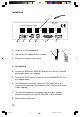
Installation
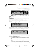
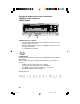
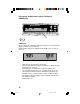
1. Attach up to 12 thermocouples.
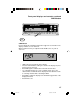
2. Connect the AC adapter to the instrument.
3. Plug the AC adapter into an outlet.
4 - 7 are Optional
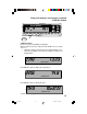
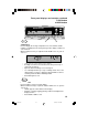
4. Connect the PARALLEL PRINTER output to a PC printer (standard
parallel port cable - not supplied).
5. Connect the PC/IN jack to a serial port of your WINDOWS PC (use
the supplied cable).
6. To interconnect instruments connect the OUT/LINK jack of one
Scanning Thermocouple Thermometer to the PC/IN jack of the next
(cable supplied).
7. To control printing or data storage by external events, connect
momentary contact events to the TRIGGER + GND connector.
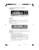
8. Switch power switch to on.
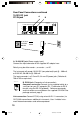
10-28 VDC
7-20 VAC
500 MA
12 CHANNEL TERMOCOUPLE SCANNER
PARALLEL PRINTER
TRIGGER
+ GND
OUT/LINK
RS-
232
MODEL ####-##
Mfg. By Barnant Company
Barrington, IL 60010-2392
USA
1
7
2
8
3
9
4
10
5
11
6
12
PC/IN
1
8256 4 7
2
3
BA 1-12 10/12/01, 11:01 AM12