XPV Peristaltic Pump Installation, Operation and Maintenance Manual Tested and Certified by WQA against NSF/ANSI 61-Section 8. and CSA B483.1 REV.
TABLE OF CONTENTS 1. 2. 3. 4. 5. Introduction .................................................................................................... 3 Safety Instructions ......................................................................................... 4 Technical Specifications ................................................................................ 6 Installation...................................................................................................... 7 Operation ...............
1. Introduction Thank you for your purchase of the Chem-Tech Series XP peristaltic pump from Pulsafeeder. We appreciate your decision to purchase a Pulsafeeder product. Please take this time to become familiar with your pump and the number of accessories that shipped with your product. The shipping box contains the following items: 1) Peristaltic pump comprising of: (a) pump head and tube assembly, (b) clear polycarbonate splash guard with locking thumb screw, and (c) snap-on rear splash guard.
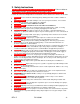
2. Safety Instructions READ AND UNDERSTAND ALL INSTRUCTIONS PRIOR TO USE. Failure to follow or understand instructions can/may lead to serious injury or death. LISEZ ET COMPRENEZ TOUTES LES INSTRUCTIONS AVANT L'UTILISATION. L'échec de suivre ou comprendre les instructions causer la blessure sérieuse ou la mort. WARNING: Secure chemicals & metering pumps, making them inaccessible to children & pets.
WARNING: Only finger tighten plastic connections (Do not use a wrench). AVERTISSEMENT: Seulement le doigt se serre les connexions de plastique (n'utilisez pas de tourne-à-gauche). WARNING: Consult licensed plumber and electrician before installation to be sure to conform to local codes. AVERTISSEMENT: Consultez le plombier autorisé et l'électricien avant l'installation pour être sûr de vous conformer aux codes locaux.
3. Technical Specifications Refer to the data plate located on the back of the peristaltic pump. Note that the data plate will be located behind the back splash cover if installed. Please make note of the Electrical Rating, Feed Rate and Maximum Pressure of the pump.
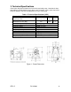
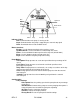
4. Installation Vertical Mount NOTE: For pumps operating in swimming pool installations the pump is to be supplied by an isolating transformer or through a residual current device (RCD). 1) The pump can be installed either vertically or horizontally (See Figure 2). Make sure to secure the pump on a flat level surface that will support 50-lbs (22kg) and secure with four .25-in (6mm) screws in the holes provided. The guard snaps into the back of the pump via three tangs - see Figure 1.
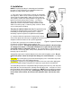
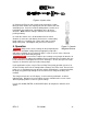
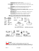
Figure 4: Injector valve 5) Referring to Figure 5 slide ceramic strainer weight on suction tubing first then remove the coupling nut from the strainer and slide onto tubing next. Push the end of the tubing onto the strainer and hand tighten the coupling nut. Hand-tighten only, do not use wrenches. Note: Immerse tubing in hot water to soften prior to pushing on fitting.
Run Up Arrow Stop Fault Down Arrow Prime Stop Escape Enter Indicator Lights: Run: Illuminated when the pump is running or idle Stop: Illuminated when the pump is stopped by the external stop signal Fault: Illuminated when a fault condition occurs Button functions: Escape: Use this button to go back to the previous screen Up/Down Arrow: Use these buttons to scroll through the menus Prime: Push and hold this button to prime at fixed speed (default 100%) Enter: Use this button to choose/accept menu lines
Software Ver: Indicates software version Troubleshoot: Shows various system inputs to aid startup issues W-Meter Input: W-Meter: Selects the type of water meter being used (dry contact or Hall Effect) Volume/Kfact: Sets the water meter volume per pulse or K-factor Flow Units: Sets the units for flow display (gallons or liters) Relay Output: Stop Input: Relay activates when the stop input is active Low 4-20 Alrm: Relay activates when 4-20mA input drops below the low 4-20mA alarm point Hi 4-20 Alrm: Relay act
AVERTISSEMENT: N'ESSAYEZ PAS DE NOURRIR DES PRODUITS CHIMIQUES SANS PREMIÈRE CONSULTATION DE VOTRE COMMERÇANT DE MANGEUR CHIMIQUE OU FOURNISSEUR CHIMIQUE. Pour éviter de manquer du produit chimique, suivez un programme régulier de contrôler des réserves chimiques. CAUTION: Inspect peristaltic tubing frequently and replace when deterioration becomes apparent. Peristaltic tubing will eventually wear and break if neglected.
Figure 7a: Pump Head Assembly with Front Cover Attached Figure 7b: Pump Head Assembly with Front Cover Removed 4) Remove the two thumb screws holding on the pump head cover and remove - See figure 7b above. 5) Remove pump head tube assembly by removing both connector fittings and pulling tubing straight out of the pump head. Tubing may retain a small amount of chemical. 6) Remove rotor assembly by pulling straight out of pump head. 6.2.
1) Reinstall the rotor assembly by aligning the cross in the rotor to the drive shaft cross and fully insert into pump head. 2) Use the Prime button and align the rotor assembly as shown in Figure 9a. Note position of tube and rotor’s cut-away guide slot. Figure 9a: Rotor Alignment at Start of Tube Installation 3) Insert one connector end of the tubing assembly into the bottom retaining slot in the pump head. Insert the tube through the guide slot in the rotor.
Figure 9c: Finishing the New Tube Installation 6) Using the Prime button, run the pump for several revolutions and then fully tighten the thumb screws hand tight. 7) Return the pump to service by following the procedures in the installation section. 6.3.
For warranty and service matters within the European Union, contact the seller or: PULSAFEEDER, INC. STEIGAR 24 NL 1351 AB ALMERE NETHERLANDS 7.2. Returns The Customer Service Department will issue a Return Authorization (RA) number for all returns. The following information will be required: 1. Billing and a ship-to address. 2. Model and serial number. 3. Contact name and phone number. 4. Reason for return. 5. Purchase order (where applicable). 6. RA number on outside of the carton. 7.
Appendix I. Pump Assembly REV.
II. Pump Head and Tube Assemblies REV.
Date Maintenance Performed III. Notes: IV. Installation (Use gridlines to map out pump installation) REV.
8. Parts Chem-Tech XP Series Spare Parts U8800712 ¼” OD Tubing Injection valve assembly U8800705 3/8” OD Tubing injection valve assembly Strainer assembly J60609 (1/4” Tubing) J60664 (3/8” Tubing J63049 Optional Weather shield. 03-174-02 Injection valve ½” MNPT adapter NC110002 PVC Suction and discharge Coupling Nut, .25 NPT NC110016-000 Suction and discharge tubing Sleeve, .25 OD Tube J63004 Rain Shield U0818286 ¼” OD Suction and discharge tubing 15 feet (4.