READ ALL CAUTIONS CAREFULLY BEFORE INSTALLING PUMP NOTE: Prime Performance Series Addendum starts on page 13 INSTRUCTION MANUAL P/N 32040 Rev B
TABLE OF CONTENTS Page SAFETY INSTRUCTIONS ......................................................................................................................................... 2 INTRODUCTION ........................................................................................................................................................ 2 PRECAUTIONS FOR OPERATION ..........................................................................................................................
MANUFACTURER’S PRODUCT WARRANTY The manufacturer warrants its equipment of its manufacture to be free of defects in material or workmanship. Liability under this policy extends for twenty-four (24) months from the date of purchase or one (1) year from date of installation or whichever comes first. The manufacturer’s liability is limited to repair or replacement of any device or part which is returned, prepaid, to the factory and which is proven defective upon examination.
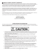
10. Standard white polyethylene discharge tubing is not recommended for installations exposed to direct sunlight. Consult supplier for special black polyethylene tubing. 11. Manufacturer will not be held responsible for improper installation of pumps, or local plumbing conducted. All cautions are to be read thoroughly prior to hook-up and plumbing. For all installations a professional plumber should be consulted. Always adhere to local plumbing codes and requirements. 12.
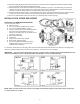
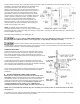
Flooded suction mounting Fig. C (installing feeder at the base of tank on a platform) is the most trouble free type of installation. (Tank stands and platforms are available for all size feeders and tanks). The pump is secured on the platform, and then the clear suction tubing is attached to a bulkhead fitting assembly and the suction valve housing on the pump head.
DOWN-THE-WELL INSTALLATION: Often it is desirable to provide chemical feed near the intake of the well pump for additional retention time and mixing of the chemicals. An additional length of discharge tubing will be required for this installation. Secure the end of the discharge tubing to the pump cylinder, drop pipe, or foot valve and lower it into the well. An antisiphon valve must be installed on systems such as this where the discharge is lower than the feeder and the chemical storage tank.
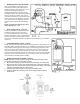
5. Install the bypass tubing from the kit into the bypass port of the bleed valve and hand tighten the coupling nut. Bypass tubing should be connected to return bypassed liquid back to the solution tank. 6. Install the discharge tubing into the discharge port of the bleed valve and hand tightens the coupling nut. 7. Return the system to operating conditions and reconnect the power to the pump. The pump is now ready for priming and operation.
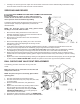
All air must be purged from the pump head before the pump will pump against pressure. Turn on the power to the pump. Loosen the locking lever by turning it counter-clockwise and turn the output adjusting knob counter-clockwise to full capacity, (one full turn only) then tighten the locking lever by turning clockwise to a hand tight position. Solution should be primed to the head within a few minutes. (Refer to Figure K) Air Bleed Operation: A) While pump is running, turn adjustment screw counterclockwise.
7. A setting of "0" will now give zero output. One full revolution of the knob counter clockwise will give maximum output. The knob should never be turned more than one full revolution. SERVICING AND REPAIRS REPLACEMENT OF PUMP HEAD ASSEMBLY OR DIAPHRAGM: Before performing any repairs on Series 100/150 chemical feeders, be sure to disconnect all electrical connections and relieve pressure from suction/discharge tubing. The Series 100/150 feeder was designed so that servicing can be quick and simple.
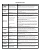
TROUBLESHOOTING PROBLEM PROBABLE CAUSE 1. Pump setting too low. LOSS OF CHEMICAL RESIDUAL 2. Scale at injection point TOO MUCH CHEMICAL LEAKAGE AROUND TUBING CONNECTIONS 3. Solution container allowed to run dry 1. Pump setting too high. 2. Chemical in solution tank too rich. 3. Siphoning of chemical into well or main line 1. Worn tube ends 2. Chemical attack 1. Leak in suction side of pump. 2. Valve seats not sealing. 3. Low setting on pump. FAILURE TO PUMP OR FEED 4. Low solution level. 5.
Chem-Tech Prime Performance Series Addendum Addendum Chem-Tech Prime Performance Degassing Pump Head Instructions NOTE: Head is for use on 15, 24 and 30 GPD models only!! Before performing any maintenance or repairs on chemical metering pumps, be sure to disconnect all electrical connections and insure that all pressure valves are shut off and pressure in the pump and lines has been bled off.
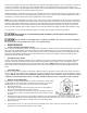
Chem-Tech Prime Performance Series Addendum 4. Connect the return tubing to the degas valve on the top of the pump head. 5. Secure the other end of the degas return tubing to the top of the solution tank above the level of the chemical. TIP: For best results, insure the strainer / tubing hangs vertically and is as short as possible with the strainer near the bottom of the solution tank but above any sediment, see figure 1.
Chem-Tech Prime Performance Series Addendum ITEM AS'Y AS'Y AS'Y AS'Y 1 2 DEGAS RETURN 3 4 NOTE NOTCH ON TOP 5 PART # J60176 J60178 J60180 J60182 J28869 J41805 J41806 J41807 J41808 J41809 J41810 J41811 J41812 J41813 J41814 J32079 PART DESCRIPTION HEAD AS'Y, S100 DEGAS HYP.5in.-T 15,24,30 HEAD AS'Y, S100 DEGAS HYP.38in.-T 15,24,30 HEAD AS'Y, S100 DEGAS VTN.5in.-T 15,24,30 HEAD AS'Y, S100 DEGAS VTN.38in.-T 15,24,30 HEAD(PVC), S100 DEGAS MOLDED VLV AS'Y, DEGAS PVC/TFE/CER, .50in.