Instruction Manual 2700 Series Benchtop Meters pH 2700 ● ION 2700 ● CON 2700 ● DO 2700 ● PC 2700 sales@novatech-usa.com www.novatech-usa.com Tel: (866) 433-6682 Fax: (866) 433-6684 Tel: (281) 359-8538 Fax: (281) 359-0084 Technology Made Easy ...
TABLE OF CONTENTS 1. Introduction......................................................................................1 2. Getting Started.................................................................................2 Keypad and Display ...................................................................................................2 Navigation of Tabs .....................................................................................................3 Meter Connections ..............................
Sample ID ....................................................................................................................27 Measure Unit...............................................................................................................27 Alarm ...........................................................................................................................27 Cal Due .....................................................................................................................
1. Introduction Thank you for selecting our 2700 series research benchtop meter. This microprocessor-based instrument incorporates a large LCD for clear viewing, yet offers a small footprint to conserve space. Each meter includes a convenient slide-out calibration card for quick reference. All models (except for DO 2700) include an electrode arm and metal bracket which can be easily attached to the left or right side of the meter according to your preference.
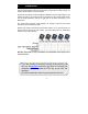
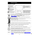
2. Getting Started Keypad and Display Auto Read is enabled. When flashing, the instrument has detected a ‘Stable’ reading and locked the value. Press MEAS to resume live reading. See Section 3—Auto Read to disable this feature, or go to SETUP…SYSTEM…AUTO READ. Based on the stability criteria settings in System Setup, the instrument has detected a stable reading. Password Protection: Enabled. Requires password for all calibration and setup menus Password Protection: Disabled.
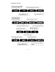
Navigation of Tabs 3
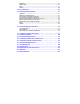
Meter Connections pH 2700 ION 2700 PC 2700 CON 2700 DO 2700 DC RS-232 CON/TEMP Power supply RS-232 output, 2.5 mm jack for RS-232 cable 8-pin DIN connection for 2-cell or 4-cell Con/TDS/Temp electrodes DO 8-pin DIN connection for Dissolved Oxygen/Temp self stirring electrode ATC For Automatic Temperature Compensation probe. For PC 2700, this corresponds to the temperature measurement associated with the BNC (“pH”) input. REF Pin connection for half cell reference electrodes.
3. System Setup & Configuration Use the System Setup to customize operation of your 2700 series meter. from the measurement screen and then press ENTER when Press SYSTEM is highlighted to access these settings.
Stability Criteria The 2700 allows adjustment of the Stable indicator which relates to how fast and frequent it appears. There are three levels of adjustment; SLOW, MEDIUM, & FAST. To display a ‘Stable’ reading more quickly and more often, use “FAST” setting. MEDIUM or SLOW is recommended for most applications. When Auto Read is enabled, a stability criteria setting of “SLOW” is recommended to for best results. SLOW: The Stable indicator will take longer to appear and will appear less frequently.
Data Log (storing data to internal memory) Select “SINGLE” to manually save one point at a time. Press the “MEM IN” function key any time during measurement to save data. Select “TIMED” to automatically save data at selectable intervals— ranging from 3 to 3600 seconds. Data will be collected until the data limit is reached or until “SINGLE” data log is selected. This feature is useful for gathering data from a single sample over time. Note that “MEM IN” is not available during TIMED setting.
Date & Time Setting the correct date and time is required for GLP and will apply to power off, measurement, data log, and print functions. Instrument has battery backup to retain date/time settings upon power loss. Factory reset will not apply to date and time setting once it has been set. Changes related to daylight savings time must be manually entered.
Factory Reset Select “YES” to reset the 2700 to the factory default settings except; Date & Time, Temperature calibration, and data stored in memory. Contrast Adjustment Optimize the contrast setting of your 2700 display for best visibility in your surrounding lighting conditions. Test various contrast settings for best results. This setting will be applied to both backlight and non-backlight conditions.
4. Setup pH & mV Use Setup pH or mV mode to customize these parameters. Note: mV setup offers Sample ID and Alarm setting only. from the measurement screen and then press ENTER when pH Press or mV is selected. Sample ID This is a user selectable number from 1 to 99999. Incorporating a sample ID to identify one or more data points is useful to distinguish data that is saved into memory or sent to a PC or printer. Use the up/down arrow keys to adjust the values and left/right arrow keys to move the cursor.
Cal Points Specify the number of pH calibration points you intend to calibrate with. Select the number of calibration points from 1 to 5 with preset buffer groups or from 2 to 5 points with custom buffer group.
5. pH Calibration (with preset buffer group) For best results, periodic calibration with known accurate standards is recommended prior to measurement. Calibrate with standards that bracket your intended measuring range while including a neutral point (7.00, 6.86, or 6.79). For example, if you expect to measure samples from pH 6.2 to 9.5, calibration with 4.01, 7.00, and 10.01 will work well. The 2700 series meters can be calibrated with up to 5 preset or custom buffers (up to 6 with DIN buffer group).
If the meter is password protected, you will be prompted to enter a password. See Section 3—Password. 4) The primary display is the un-calibrated measured value. The 2700 automatically searches for and selects the appropriate value from your buffer group in the secondary display. This value will blink when the ‘Stable’ indicator appears. Selecting CLR-C will clear the existing calibration. 5) Press ENTER to accept the calibration value of the measured buffer.
6. pH Calibration (with custom buffers) Buffer Group CUSTOM pH Values Any 2 - 5 values, ≥ 1.0 pH unit apart 1) Turn meter on, press MODE if needed for pH measurement mode. 2) Rinse the pH and ATC electrodes then submerse in your custom pH buffer— any pH value can be used. 3) Press CAL (enter password if required) to enter calibration mode. If desired, select CLR-C to clear the previous calibration. The lower pH value corresponds to the factory default setting for reference.
5) Rinse the pH and ATC electrodes then submerse in next custom pH buffer. Use any pH value that is at least 1.0 pH unit from custom pH standards that have already been calibrated. 6) Repeat Step 5 with additional pH buffers (up to 5 custom buffers) in any order. Press ESC to escape and save your calibration at any time. When the specified number of calibration points is met, the pH calibration report page is automatically displayed.
7. Millivolt (mV) Calibration (Offset Adjustment) Oxidization Reduction Potential (ORP or Redox) as measured by an ORP electrode in mV units is not a precise measurement, but is useful as a relative indicator. As such, mV offset adjustment is not meant to enhance accuracy, but rather to make readings comparable to a reference. Commercial ORP solutions are commonly used as a check standard—a meter/electrode system is verified to be close to a given value although adjustments are not made.
8. Temperature Setup Use Setup Temperature mode to desired temperature units; º C or º F. from the measurement screen and then press ENTER when Press TEMPERATURE is selected. Choose º C or º F temperature units of measure. Automatic Temperature Compensation (ATC) is automatically applied when a temperature sensor is connected. Manual Temperature Compensation (MTC) of 25 º C is used if the temperature sensor is not connected. See Section 9—Temperature Calibration to adjust the MTC temperature value.
9. Temperature Calibration The thermistor sensor used for automatic temperature compensation and measurement is both accurate and stable, so require frequent calibration isn’t required. Temperature calibration is recommended upon electrode replacement, whenever the temperature reading is suspect, or if matching against a certified thermometer is desired. 1) Connect the temperature probe to the meter and place into a solution with a known accurate temperature such as a constant temperature bath.
10. Conductivity, TDS, Salinity, & Resistivity Setup Use Setup mode to customize Conductivity, TDS, Salinity, & Resistivity parameters. from the measurement screen and then press ENTER when Press Conductivity, TDS, Salinity, or Resistivity is selected. Sample ID This is a user selectable number from 1 to 99999. Incorporating a sample ID to identify one or more data points is useful to distinguish data that is saved into memory or sent to a PC or printer.
automatic calibration is recommended. Otherwise, manual calibration should be selected. The factory default is automatic conductivity calibration. Note that automatic calibration is not available for conductivity range 1. Cal Points Use SINGLE for Single-Point Calibration (SPC) to apply a single calibration value across all ranges. Use MULTI for Multi-Point Calibration (MPC) to calibrate each range individually. This will restrict an individual calibration so that it is applied to one range only.
Note: this option does not apply to Salinity mode. For more information, see Section 20—Calculating Temperature Coefficients. Normalization Temperature (°C) When Automatic Temperature Compensation is used, measurements are adjusted by the temperature coefficient to the normalization temperature. Adjust the value from 15.0 to 35.0 º C. Note: Use the normalization temperature that is referenced on your calibration standard(s). This will usually match the 2700 factory default value (25 º C).
Alarm The 2700 offers a visual and audible alarm to alert you when the High or Low values that have been set from this menu are exceeded. “High Alarm” or “Low Alarm” will blink on the display if the values are exceeded while simultaneously, a loud, intermittent beeping sound is heard. The alarms will continue until the conditions are no longer met, and will only be active during measurement mode.
11. Conductivity Calibration (automatic) For best results, periodic calibration with known accurate standards is recommended prior to measurement. Calibrate with standards that are close in value to your intended sample(s). When using multi-point calibration, perform a calibration in each range that you expect to use for best results. If the conductivity electrode has been stored dry for some time, soaking in alcohol or clean water for a few minutes can help performance.
5) For multi-point calibration repeat steps 2 & 3 with additional standards. Press ESC to save the calibration, or press NEXT to view the calibration report. Calibrate one point per range, up to 4. Additional automatic conductivity calibration notes: A maximum of one calibration point per range can be performed. If multiple calibration points are used in the same range, the most recent one will replace the previous one.
12. Conductivity, TDS, Salinity, & Resistivity Calibration (manual adjustment) For best results, periodic calibration with known accurate standards is recommended prior to measurement. Calibrate with standards that are close in value to your intended sample(s). When using multi-point calibration, perform a calibration in each range that you expect to use for best results. If the electrode has been stored dry for some time, soaking in alcohol or clean water for a few minutes can help performance.
Before and after a manual calibration 5) For multi-point calibration repeat with additional standards. Press ESC to save calibration or press NEXT to view the calibration report. Calibrate one point per range, up to 5 points. Additional manual calibration notes: A maximum of one calibration point per range can be performed. If multiple calibration points are used in the same range, the most recent one will replace the previous one.
13. Ion Setup Use Setup Ion mode to customize this parameter. Press measurement screen and then press ENTER when ION is selected. Sample ID This is a user selectable number from 1 to 99999. Incorporating a sample ID to identify one or more data points is useful to distinguish data that is saved into memory or sent to a PC or printer. Use the up/down arrow keys to adjust the values and left/right arrow keys to move the cursor. Measure Unit Select ppm, molar, or mg/L ion concentration units.
Cal Due When enabled, the “Cal Due” indicator blinks if the number of days since the last calibration has been exceeded. Set the number of days from 1 to 31. Refer to your Ion Selective Electrode instruction manual for details on conditioning, storage, maintenance, calibration standard preparation, Ionic Strength Adjustment, troubleshooting, etc. Each ISE is unique and requires care and operation that is specific to the electrode and ion of interest.
14. Ion Calibration The ION 2700 can measure ion concentration such as ammonia or fluoride when using an ion selective electrode (ISE) for the specific ion of interest. Ion calibration is required with at least two standards from (8) available values; 1.0.001, 0.01, 0.1, 1, 10, 100, 1000, and 10000. The primary display will show “- - - -” when ion calibration is required for ion measurement. Prepare ion calibration standards that bracket your measurement range.
Before and after a two point ion calibration using 0.001 and 0.01 standards 5) The mV/decade slope value will be displayed if the calibration is successful. “Slope Error” indicates that the calibration for the current point was not successful. This occurs when the slope (mV difference between two consecutive points) is < 15 mV/decade or > than 90 mV/decade. 6) Repeat steps 4 & 5 with additional ISE standards or press ESC to escape and save your calibration.
15. Dissolved Oxygen Setup Use Setup Dissolved Oxygen mode to customize the parameter. Press from the measurement screen and then press ENTER when DO% or DO (mg/L) is selected for percent saturation or concentration modes respectively. Note that setup parameters differ slightly depending on which is selected. Sample ID This is a user selectable number from 1 to 99999.
Pressure Cal (% saturation mode only) The DO 2700 includes a built-in barometer that is factory calibrated. While frequent pressure adjustment is not required, adjustments can be made in the Adjusted Pressure field. The Measured Pressure is the active pressure value measured by the DO 2700. Note: if adjusting, “true” barometric pressure—that has not been corrected to sea level, must be used.
Salinity Value (concentration mode only) Enter the salinity value of your samples in parts per thousand (ppt) units. Select from 0 to 50.0 ppt. Alarm The 2700 offers a visual and audible alarm to alert you when the High or Low values that have been set from this menu are exceeded. “High Alarm” or “Low Alarm” will blink on the display if the values are exceeded while simultaneously, a loud, intermittent beeping sound is heard.
16. Dissolved Oxygen Calibration The DO 2700 utilizes a self-stirring polargraphic electrode with a built-in temperature sensor. The electrode is designed for use in BOD bottles. Power the meter on 5-15 minutes before calibration or taking a measurement as this will allow adequate time for the electrode to warm up. Longer warm up times are recommended when the membrane cap and/or electrolyte in replaced—this permits the probe to use up all oxygen retained inside the cap.
0% Calibration 7) After completing steps 1 thru 6 for 100% saturation calibration, place your electrode in zero oxygen solution (0.08M sodium sulfite). Continuous stirring is not required. 8) The primary reading is the current measured value. Be patient—the reading can take several minutes to reach 0% saturation! 9) When the reading has finally stabilized and locked on 0% press ENTER to confirm the calibration.
Additional dissolved oxygen calibration notes: • Keep the membrane free from contact with solid objects. • Use with aqueous solutions only. • Do not submerse the probe past the immersion limit (see below). • See Section 22—DO Electrode Maintenance for additional information. • Calibration adjustment is limited to ±40% of the factory default value to prevent erroneous calibrations. • If % calibration is attempted with a value of 10.1% to 49.9%, a “Calibration Error” will result.
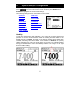
17. Transferring and Printing Data To send data directly to a printer or PC, connect the 30X427301 / 35420-01 cable to the RS-232 output port of the 2700. To connect to a USB port, an additional adapter cable is required; see Section 25—Replacements & Accessories. The 2700 can be used to: • Print/send one or more data points directly to a dedicated printer or to a PC. Press PRINT from measurement mode or from the MEM OUT screen. • Print/send the calibration report to a printer or PC.
18. Calibration Report Calibration report provides detailed information on the most recent calibration. It includes date & time, calibration standard(s), offset, temperature, number of days calibration is over due slope information, etc. The calibration report is automatically displayed after a complete calibration. from the To view the calibration report at any other time, press desired measurement screen. To send the calibration report to a printer or PC, press .
19. Dissolved Oxygen Theory Dissolved Oxygen (DO) refers to the volume of oxygen that is contained in water. There are two main sources of DO in water; atmosphere and photosynthesis. Waves and tumbling water mix air into the water where oxygen readily dissolves until saturation occurs. Oxygen is also produced by aquatic plants and algae during photosynthesis. The amount of DO that can be held by water depends on 3 factors: 1.
another way to analyze DO levels. % saturation is the measured DO level divided by the greatest amount of oxygen that the water could hold under various temperature and atmospheric pressure conditions multiplied by 100. What Is Being Measured? DO probes respond to the partial pressure of oxygen in liquid or gas being measured—they measure the “pressure” of oxygen rather than concentration.
Applications Oxygen is essential for fish, invertebrate, plant, and aerobic bacteria respiration. DO levels below 3 ppm are stressful to most aquatic organisms. Levels below 2 or 1 ppm will not support fish. Fish growth and activity usually require 5 to 6 ppm of DO, an important consideration for Aqua-culture industry. Low DO indicates a demand on the oxygen of the system. Natural organic material such as leaves accumulate in the stream and create an oxygen demand as it is decomposed.
20. Calculating Temperature Coefficients To determine the temperature coefficient of your sample solution use this formula: Where: tc = Temperature coefficient 25 = 25 ºC CT1 = Conductivity at Temp 1 CT2 = Conductivity at Temp 2 T1 = Temp 1 T2 = Temp 2 A controlled temperature water bath is ideal for this procedure. 1.
21. Calculating TDS Conversion Factor You can calibrate TDS using the value of the calibration standard solution at a standard temperature such as 25 ºC. To determine the conductivity-to-TDS conversion factor use the following formula: Factor = Actual TDS ÷ Actual Conductivity @ 25 ºC • Actual TDS: Value from the solution bottle label or as a standard made using high purity water and precisely weighed salts.
22. DO Electrode Maintenance Changing the Membrane Cap The DO 2700 electrode utilizes a cap attached to a pre-installed membrane that is easily replaced. Replace the membrane cap if it becomes damaged or worn over time as needed. When calibration can not be completed, look to replace the electrolyte first as this may help. Replace the membrane cap and electrolyte together using the following procedure. 1) Unscrew the old membrane cap from the probe.
23. Troubleshooting Parameter Cause Solution pH Won’t accept 1st calibration point New calibrations must begin neutral standard (7.00 or 6.86) pH Cal points are too close Custom pH buffer calibration values must be at least 1.0 pH unit apart. pH Reading is 7.00 and won’t change Electrode tip may be cracked broken. Replace electrode. pH or Ion Slope error Calibration error / Calibration values are too far apart, or too far from ideal values.
sensor. DO Instrument will not read zero in sodium sulfite solution Solution contains oxygen—use fresh solution. Temperature Instrument reads inaccurate temperature Calibrate using water bath or known accurate thermometer. Faulty thermistor—repair or replace. ALL Main digits are faded in measurement mode &/or are faded too often. When “Stability” is enabled, the digits on the primary reading will be faded when unstable, becoming solid when stable.
24. Specifications We reserve the right to make changes, improvements and modifications to the specifications listed here. pH pH 2700, ION 2700, PC2700 only Range Resolution Accuracy Cal. Points Buffer Sets Slope Display Temp Compensation Temp Range (Meter) Inputs -2.000 to 20.000 pH 0.1 / 0.01 / 0.001 pH ±0.002 pH + 1 LSD Up to 6 preset or 5 custom USA, NIST, DIN, User1, User2, Custom Yes (with offset) Automatic or Manual (0 to 100 ºC / 32 to 212 ºF) 0.0 to 100.0 ºC / 32.0 to 212.
Conductivity CON 2700, PC 2700 only Range Resolution Accuracy 0.050 µS to 500.0 mS 0.01 / 0.1 µS; 0.001 / 0.01 / 0.1mS ±1% full scale Automatic (4 points); Maximum 1 per range Manual (5 points); Maximum 1 per range 0.010 to 10.000 Linear & Pure; 0.000 to 10.000% 15.0 to 30.0 ºC / 59.0 to 86.0 ºF Automatic with supplied cell or Manual 0.0 to 100 ºC / 32.0 to 212.0 ºF (0.0 to 80 ºC / 32.0 to 176.0 ºF with supplied cell) Cal.
Dissolved Oxygen DO2700 Range Resolution Accuracy Offset Adjustment Cal. Points (%) Salinity Correction Barometric Pressure Correction Temperature 0 to 50.00 mg/L 0.01 mg/L ±0.5% full scale ±10.0% 2 points; 0%, 100% 1 point; ± 50% from the factory default value. Minimum reading allowed is 2.00. 0 to 50.0 ppt (manual input) 450 to 825 mmHg (automatic with built in sensor); adjustable ±150 mmHg 0.0 to 50.0 ºC / 32.0 to 122.
25.
pH 6.86 buffer solution, 480 mL bottle ECBU686BT 00654-03 pH 7.00 buffer solution, 480 mL bottle ECBU7BT 00654-04 pH 9.18 buffer solution, 480 mL bottle ECBU918BT 00654-07 pH 10.01 buffer solution, 480 mL bottle ECBU10BT 00654-08 pH 12.45 buffer solution, 480 mL bottle ECBU12BT 00654-12 pH 4.01, 7.00, & 10.
26. Warranty This meter is supplied with a warranty against significant deviations in material and workmanship for a period of THREE years from date of purchase whereas probe with a SIX -month warranty. If repair or adjustment is necessary and has not been the result of abuse or misuse within the designated period, please return – freight pre-paid – and correction will be made without charge.
27. Return of Items Authorization must be obtained from our Customer Service Department or authorized distributor before returning items for any reason. A “Return Material Authorization” (RMA) form is available through our authorized distributor. Please include data regarding the reason the items are to be returned. For your protection, items must be carefully packed to prevent damage in shipment and insured against possible damage or loss.
54
55
For more information on our products, please contact our channel partner or visit our websites listed below: Oakton Instruments 625 E Bunker Court Vernon Hills, IL 60061 USA Tel: (1) 888-462-5866 Fax: (1) 847-2472984 info@4oakton.com www.4oakton.com Distributed by : Eutech Instruments Pte Ltd Blk 55, Ayer Rajah Crescent, #04-16/24 Singapore 139949 Tel: (65) 6778 6876 Fax: (65) 6773 0836 sales@novatech-usa.com eutech@thermofisher www.novatech-usa.com .com Tel: (866) 433-6682 Fax: (866) 433-6684 www.