
User's Manual


10
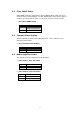
2.5 LCD Panel Shift Clock/Panel VCC Select
This jumper is for the setting of LCD panel shift clock mode and panel
power voltage.
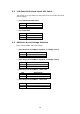
• JP7: LCD Panel Shift Clock
JP7 Description
1-3 Inverted
3-5 Normal
• JP7: Panel VCC
JP7 Description
2-4 +5V
4-6 +3.3V
2.6 COM Port RI and Voltage Selection
JP8 is setting COM3, 4 RI and Voltage.
• JP8: Set pin 9 of COM3 as signal RI or voltage source
JP8 Description
10-12 COM3 RI Pin Use RI
8-10 COM3 RI Pin Use Voltage
• JP8: Set pin 9 of COM4 as signal RI or voltage source
JP8 Description
9-11 COM4 RI Pin Use RI
7-9 COM4 RI Pin Use Voltage
• JP8: Set pin 9 of COM3 as +5V or 12V
JP8 Description
2-4 COM3 RI Pin Use Voltage +5V
4-6 COM3 RI Pin Use Voltage +12V
• JP8: Set pin 9 of COM4 as +5V or 12V
JP8 Description
1-3 COM4 RI Pin Use Voltage +5V
3-5 COM4 RI Pin Use Voltage +12V